The Chain DualKey is a programmable dual-button input development board. Its factory firmware allows you to configure button functions and RGB LED colors, as well as other Chain series devices connected via the Chain Bus.
Ready to unleash its full potential? This guide will walk you through everything from firmware flashing via M5Burner to advanced Web-based configuration. Master the core essentials in minutes and make your desktop setup smarter and more efficient.
🏷️Firmware Update
A new firmware version has been released, adding support for more key-mapping features. It is recommended to use M5Burner for one-click updating. Refer to the product page for instructions on entering Download Mode and connecting the device to your computer. After that, download M5Burner. In the left panel, select the device type Chain DualKey. On the right, you will see Chain DualKey User Demo — click Download - Burn to update the firmware. Once the update is complete, power-cycle the device to apply the new firmware.
Steps
1. Button Numbering
In the factory firmware, the two buttons on Chain DualKey are named Key1 (Left Key) and Key2 (Right Key):
2. Switch Positions
OFF USB: When the switch is in the middle position, Chain DualKey is turned off when not connected to an external power source, and operates in USB wired mode when connected (will also enable BLE and Wi-Fi).
BLE / Wi-Fi: When the switch is toggled to the left or right, both modes function identically in this firmware, enabling BLE and Wi-Fi.
🏷️About Battery Charging
Whenever an external power source is connected, the battery will charge regardless of the switch position.
3. Connecting to Host as Keyboard
Wired Connection: Use a USB-C cable to connect the Chain DualKey to a computer, smartphone, or other host device.
Bluetooth Connection: Power the Chain DualKey via an external power source or toggle the switch to left / right side. On your computer, smartphone, or other host device, connect to the Bluetooth device named DualKey-XXXX (XXXX is a four-character alphanumeric code used to distinguish different devices). When a pairing code dialog appears, simply confirm it. This firmware supports pairing and connecting to only one Bluetooth host at a time. To connect to another host, unpair it from the currently paired device first.
Chain DualKey can connect to two devices simultaneously — one via a wired connection and the other via Bluetooth.
🏷️Notes for Each Operating System
macOS: When connecting for the first time, a Keyboard Setup Assistant will appear—click Quit to skip it. This does not affect normal use. iOS: When an external keyboard is connected, the on-screen keyboard may be disabled in some cases, allowing input only from Chain DualKey. Windows / Android: No specific issues have been observed; behavior may vary depending on system version and settings.
4. Configuration Web Page
Power the Chain DualKey via an external power source or toggle the switch to left / right side. On your computer or smartphone, connect to the Wi-Fi access point (SSID: DualKey_XXXX (XXXX is a four-character alphanumeric code used to distinguish different devices), Password: 12345678), then open a browser and visit 192.168.4.1 to access the configuration web page:
The language of the page (Chinese / English) can be switched in the upper-right corner, where you can also check the Wi-Fi AP connection status and the latest update time.
In the middle-left Basic Information section, you can configure the LED colors of the two buttons and check button states (when pressed, the ring becomes darker, as shown below), switch position, and battery status. If you set both button colors to pure black (0, 0, 0), the LEDs will not turn off — instead, they will display a rainbow 🌈 color cycle!
In the middle HID Device Status section, you can set button functions, enable or disable USB wired mapping and BLE wireless mapping, and check USB and Bluetooth connection status:
Copy Paste: Simulates Ctrl+C / Ctrl+V shortcuts for copy and paste on Windows.
Copy Paste: Simulates Cmd+C / Cmd+V shortcuts for copy and paste on macOS.
Undo Redo: Simulates Ctrl+Z / Ctrl+Y shortcuts for undo and redo in certain Windows applications.
Undo Redo: Simulates Cmd+Z / Cmd+Y shortcuts for undo and redo in certain macOS applications.
Undo Redo: Simulates Cmd+Z / Cmd+Shift+Z shortcuts for undo and redo in certain macOS applications.
Tab Switch: Simulates Ctrl+Tab / Ctrl+Shift+Tab shortcuts for switching tabs in applications (such as Chrome) on both Windows and macOS.
Window Switch: Two keys simulate Alt and Tab. Holding Alt and pressing Tab repeatedly switches windows on Windows.
Window Switch: Two keys simulate Cmd and Tab. Holding Cmd and pressing Tab repeatedly switches applications on macOS.
Zoom: Simulates Ctrl+Minus / Ctrl+Plus shortcuts for zooming out and in on Windows.
Zoom: Simulates Cmd+Minus / Cmd+Plus shortcuts for zooming out and in on macOS.
Page: Simulates PgUp / PgDn page navigation keys for scrolling up and down on Windows and macOS.
Volume Control: Simulates Volume Up / Volume Down keys on Windows and macOS.
Media Control: Simulates Previous Track / Next Track media control keys on Windows and macOS.
Media Control: Simulates PlayPause / Stop media control keys on Windows and macOS.
Home Key: Simulates Home / End keys.
Arrow Keys: Simulates Up / Down arrow keys.
Arrow Keys: Simulates Left / Right arrow keys. Some of the above options also support Android and iOS; actual availability may vary by application and system.
In the middle-right Wi-Fi section, you can configure the Wi-Fi network for Chain DualKey to connect to. Enter the SSID, password, and static IP address, then click Apply. Chain DualKey will disable AP mode and connect to the specified network. You can then access the configuration page from the assigned IP address via computer or smartphone.
🏷️Resetting Wi-Fi
To reset Wi-Fi settings: press and hold both buttons for 5 seconds until the Key1 LED turns off and the Key2 LED turns on, then release both buttons. The two LEDs will flash red 3 times, then alternately flash white 3 times. Wi-Fi settings will be reset — the device will forget connected networks and re-enable AP mode.
5. Chain Bus
Chain DualKey can connect to other Chain series devices—such as Chain Key and Chain Joystick—through the Chain Bus on either side. (More Chain series devices will be released soon.)
Devices in the Chain series can be connected via Chain Bridge or Chain Return. When connecting, pay attention to the direction: the triangle arrow at the bottom of each device should point outward from the Chain DualKey (the main controller), as shown below:
At the bottom of the configuration web page, you can view and configure the functions of all devices connected to the Chain Bus:
Click a device in the top topology diagram to quickly jump to its corresponding section in the detailed device list below.
Each device's detail card shows the latest triggered events and collected data values, and allows you to adjust the indicator LED color.
Click HID Function Config to assign functions to various trigger events. Note that some trigger events may conflict with each other (especially Press, Release, and other button events). Be careful when assigning functions.
When a device generates a trigger event or data update, its detail card will flash.
Bus RGB refers to the indicator LED color for all devices on that Chain Bus (one side of the Chain DualKey).
Conclusion
With yourChain DualKey now fully configured, you are ready to enjoy a more intuitive and efficient desktop experience. From custom macros to vibrant RGB setups, this compact device is designed to evolve alongside your workflow. Stay tuned for more Chain series modules to further expand your creative setup!
Elevate Your Workflow: Configuring Your Chain DualKey with the Latest Firmware
·Powered by an ESP32-P4 SoC, with 16MB of flash memory and 32MB of PSRAM. This makes it the device with the most memory we have integrated into Home Assistant to date.
·It features a generous 5″ TFT touchscreen(1280×720), compatible with LVGL.
·Includes a front-facing 2 MP SC2356 camera(1600×1200) for capturing images and video.
·Equipped with one USB-A port, one USB-C port, and a Micro SD card slot (card not included).
·It has two expansion ports for external sensors(GROVE and M5BUS) and a connector for a LoRa antenna.
·Features two microphones, a speaker, and a 3.5mm jack, meaning you can also use it to control Assist.
·If you chose the "TAB5 Kit," it comes with a Li-ion battery that you can easily replace (allowing you to have a spare one charged and ready).
In short, these characteristics make it the perfect candidate for a portable, autonomous control device with great tactile feedback. Additionally, as it is based on an ESP32-P4, the M5Stack TAB5 can be integrated into HA via ESPHome.
Prerequisites
To integrate the M5Stack TAB5 into HA, you will first need:
·A USB-C DATA cable to power the board (you will not be able to install the software with a charge-only cable).
Configuration in ESPHome
Follow these steps to integrate the M5Stack TAB5 into HA:
1.In Home Assistant, go to your ESPHome add-on and click on New device > Continue > New Device Setup.
2.Give your device a name (for example, “M5stack Tab5”) and click “Next.”
3.For the device type, select “ESP32-C6.” You will notice in the background that a new block has been created for your device.
4.Click “Skip” and then click “Edit” on your device's block. Copy the code that appears and save it, as you will need parts of it later.
5.Copy the following code and use it to replace the previous code in ESPHome.
substitutions:

# Device customization
# Personalización del dispositivo

  name: m5stack-tab5
  friendly_name: M5stack Tab5

####################################

esphome:
  name: ${name}
  friendly_name: ${friendly_name}

esp32:
  board: esp32-p4-evboard
  flash_size: 16MB
  framework:
    type: esp-idf
    advanced:
      enable_idf_experimental_features: true

esp32_hosted:
  variant: esp32c6
  active_high: true
  clk_pin: GPIO12
  cmd_pin: GPIO13
  d0_pin: GPIO11
  d1_pin: GPIO10
  d2_pin: GPIO9
  d3_pin: GPIO8
  reset_pin: GPIO15
  slot: 1

logger:
  hardware_uart: USB_SERIAL_JTAG

psram:
  mode: hex
  speed: 200MHz

api:
  encryption:
    key: "F8WsdfddfKt1XvQV9pU32443dsfdsf"

ota:
  - platform: esphome
    password: "sdffds23b12747edfq43543"

wifi:
  ssid: !secret wifi_ssid
  password: !secret wifi_password
  ap:
    ssid: "M5Stack-Tab5 Fallback Hotspot"
    password: "sdfdMtQR34rfww"

# Sensors configuration
# Configuración de sensores

binary_sensor:
  - platform: gpio
    id: charging
    name: "Charging Status"
    pin:
      pi4ioe5v6408: pi4ioe2
      number: 6
      mode: INPUT_PULLDOWN

  - platform: gpio
    id: headphone_detect
    name: "Headphone Detect"
    pin:
      pi4ioe5v6408: pi4ioe1
      number: 7

i2c:
  - id: bsp_bus
    sda: GPIO31
    scl: GPIO32
    frequency: 400kHz

pi4ioe5v6408:
  - id: pi4ioe1
    address: 0x43
    # 0: O - wifi_antenna_int_ext
    # 1: O - speaker_enable
    # 2: O - external_5v_power
    # 3: NC
    # 4: O - lcd reset
    # 5: O - touch panel reset
    # 6: O - camera reset
    # 7: I - headphone detect
  - id: pi4ioe2
    address: 0x44
    # 0: O - wifi_power
    # 1: NC
    # 2: NC
    # 3: O - usb_5v_power
    # 4: O - poweroff pulse
    # 5: O - quick charge enable (inverted)
    # 6: I - charging status
    # 7: O - charge enable

select:
  - platform: template
    id: wifi_antenna_select
    name: "WiFi Antenna"
    options:
      - "Internal"
      - "External"
    optimistic: true
    on_value:
      - if:
          condition:
            lambda: return i == 0;
          then:
            - switch.turn_off: wifi_antenna_int_ext
          else:
            - switch.turn_on: wifi_antenna_int_ext

# The DAC Output select needs to be manually (or with an automation) changed to `LINE1` for the onboard speaker
  - platform: es8388
    dac_output:
      name: DAC Output
    adc_input_mic:
      name: ADC Input Mic

sensor:
  - platform: ina226
    address: 0x41
    adc_averaging: 16
    max_current: 8.192A
    shunt_resistance: 0.005ohm
    bus_voltage:
      name: Battery Voltage
    current:
      name: Battery Current
      # Positive means discharging
      # Negative means charging

switch:
  - platform: gpio
    id: wifi_power
    name: "WiFi Power"
    pin:
      pi4ioe5v6408: pi4ioe2
      number: 0
    restore_mode: ALWAYS_ON
  - platform: gpio
    id: usb_5v_power
    name: "USB Power"
    pin:
      pi4ioe5v6408: pi4ioe2
      number: 3
  - platform: gpio
    id: quick_charge
    name: "Quick Charge"
    pin:
      pi4ioe5v6408: pi4ioe2
      number: 5
      inverted: true
  - platform: gpio
    id: charge_enable
    name: "Charge Enable"
    pin:
      pi4ioe5v6408: pi4ioe2
      number: 7
  - platform: gpio
    id: wifi_antenna_int_ext
    pin:
      pi4ioe5v6408: pi4ioe1
      number: 0
  - platform: gpio
    id: speaker_enable
    name: "Speaker Enable"
    pin:
      pi4ioe5v6408: pi4ioe1
      number: 1
    restore_mode: ALWAYS_ON
  - platform: gpio
    id: external_5v_power
    name: "External 5V Power"
    pin:
      pi4ioe5v6408: pi4ioe1
      number: 2

# Display configuration
# Configuración de la pantalla

esp_ldo:
  - voltage: 2.5V
    channel: 3

font:
  - file: "gfonts://Kanit"
    id: font_title
    size: 100

light:
  - platform: monochromatic
    output: backlight_pwm
    name: "Display Backlight"
    id: backlight
    restore_mode: RESTORE_DEFAULT_ON
    default_transition_length: 250ms

output:
  - platform: ledc
    pin: GPIO22
    id: backlight_pwm
    frequency: 1000Hz

touchscreen:
  - platform: gt911
    interrupt_pin: GPIO23
    update_interval: never
    reset_pin:
      pi4ioe5v6408: pi4ioe1
      number: 5
    calibration:
      x_min: 0
      x_max: 720
      y_min: 0
      y_max: 1280
    id: touch

display:
  - platform: mipi_dsi
    dimensions:
      height: 1280
      width: 720
    model: M5Stack-Tab5
    reset_pin:
      pi4ioe5v6408: pi4ioe1
      number: 4
    show_test_card: true
    rotation: 90

lvgl:
  touchscreens: touch
  buffer_size: 100%
  style_definitions:
    - id: style_title
      align: CENTER
      text_font: font_title
  widgets:
    - label:
        styles: style_title
        text: 'Hola Aguacater@s!!'

# Media configuration and voice assistant
# Configuración multimedia y asistente de voz

audio_dac:
  - platform: es8388
    id: es8388_dac

audio_adc:
  - platform: es7210
    id: es7210_adc
    bits_per_sample: 16bit
    sample_rate: 16000

i2s_audio:
  - id: mic_bus
    i2s_lrclk_pin: GPIO29
    i2s_bclk_pin: GPIO27
    i2s_mclk_pin: GPIO30

media_player:
  - platform: speaker
    name: None
    id: speaker_player
    announcement_pipeline:
      speaker: tab5_speaker
      format: FLAC
      sample_rate: 48000
      num_channels: 1
    on_announcement:
      # Stop the wake word (mWW or VA) if the mic is capturing
      - if:
          condition:
            - microphone.is_capturing:
          then:
            - micro_wake_word.stop:
    on_idle:
      # Since VA isn't running, this is the end of user-intiated media playback. Restart the wake word.
      - if:
          condition:
            not:
              voice_assistant.is_running:
          then:
            - micro_wake_word.start:

micro_wake_word:
  id: mww
  models:
    - okay_nabu
    - hey_mycroft
    - hey_jarvis
  on_wake_word_detected:
    - voice_assistant.start:
        wake_word: !lambda return wake_word;

microphone:
  - platform: i2s_audio
    id: tab5_microphone
    i2s_din_pin: GPIO28
    sample_rate: 16000
    bits_per_sample: 16bit
    adc_type: external

# Commented out to avoid duplicates (see above)
# Comentado para evitar duplicidades (ver arriba)
#select:
# The DAC Output select needs to be manually (or with an automation) changed to `LINE1` for the onboard speaker
#  - platform: es8388
#    dac_output:
#      name: DAC Output
#    adc_input_mic:
#      name: ADC Input Mic

speaker:
  - platform: i2s_audio
    id: tab5_speaker
    i2s_dout_pin: GPIO26
    audio_dac: es8388_dac
    dac_type: external
    channel: mono
    buffer_duration: 100ms
    bits_per_sample: 16bit
    sample_rate: 48000

voice_assistant:
  id: va
  microphone: tab5_microphone
  media_player: speaker_player
  micro_wake_word: mww
  on_end:
    # Wait a short amount of time to see if an announcement starts
    - wait_until:
        condition:
          - media_player.is_announcing:
        timeout: 0.5s
    # Announcement is finished and the I2S bus is free
    - wait_until:
        - and:
            - not:
                media_player.is_announcing:
            - not:
                speaker.is_playing:
    - micro_wake_word.start:
  on_client_connected:
    - micro_wake_word.start:
  on_client_disconnected:
    - micro_wake_word.stop:
6.Important note: This code does not include the credentials required for the device to connect to your WiFi and your Home Assistant instance, so you must add them manually. Specifically, I am referring to the following lines from the code you copied in step 4.
# Enable Home Assistant API
api:
  encryption:
    key: "bg6hash6sjdjsdjk02hh0qnQeYVwm123vdfKE8BP5"

ota:
  - platform: esphome
    password: "asddasda27aab65a48484502b332f"

wifi:
  ssid: !secret wifi_ssid
  password: !secret wifi_password

  # Enable fallback hotspot (captive portal) in case wifi connection fails
  ap:
    ssid: "Assist Fallback Hotspot"
    password: "ZsasdasdHGP2234"
7.What you need to do is find the corresponding lines in the code (at the beginning) and add the relevant information.
8.Now, click "Save" and "Install." Select "Manual download" and wait for the code to compile.
9.Once finished, select the "Modern format" option to download the corresponding '.bin' file.
10.Connect the M5Stack TAB5 to your computer using the USB-C data cable via the side port.
11.Now go to the ESPHome Web page and click "Connect." In the pop-up window, select your board and click "Connect."
12.Now click "Install" and select the '.bin' file obtained in step 9. Click "Install" once more.
13.Return to Home Assistant and go to Settings > Devices & Services. Your device should normally be discovered and appear at the top, simply waiting for you to click the "Configure" button. Otherwise, click the "Add Integration" button, search for "ESPHome," and enter your board's IP address in the "Host" field. As always, I recommend that you assign a static IP in your router to avoid future issues if it changes.
14.Finally, go to Settings > Devices & Services > ESPHome. Click the "Configure" link for your device. In the pop-up window, check the box "Allow the device to perform Home Assistant actions" and click "Submit." This will allow us to control our devices directly from the screen.
If everything went well, you should see the following on your screen:
Additionally, with this code, you will be able to:
·Control and monitor the device's sensors in Home Assistant (such as battery percentage, activating the speaker, turning on the screen…).
·Use the screen to create your control dashboard and manage your devices.
·Expose your M5Stack Tab5 as a media player entity, allowing you to use it to play audio notifications or the radio.
·Use it as a voice assistant if you have already configured Assist.
🏷️Tips:
Each part in the code has been labeled, so any sections you are not interested in can be removed.
From here on, the way you use the panel depends on your imagination!
Turn M5Stack Tab5 into a Portable Home Assistant Control Panel
Hardware and Design
The Cardputer-Adv is an enhanced iteration of the small-form-factor computer powered by the Espressif ESP32-S3 microcontroller. In essence, the Cardputer-Adv is a slightly redesigned version of the original. Side-by-side, they differ visually only in color—the new model is white, while the previous was light gray. The shape, design, and general purpose remain identical. The "brain" of the system is still a Stamp series development board, but upgraded to the Stamp-S3A. Compared to the Stamp-S3 found in the predecessor, the "A" revision features a redesigned 3D antenna for improved connectivity and a "softer," more responsive Reset button. Note that this button is covered by a sticker, making it somewhat awkward to press. Other changes include internal LED wiring and lower power consumption. The core remains the ESP32-S3FN8 microcontroller with 8MB of Flash and 23 GPIO pins. As we have covered the ESP32-S3 extensively in previous articles, we will not repeat those technical details here. The USB-C port is used for programming the Stamp, power delivery, and charging the integrated battery.
Display, Keyboard, and Audio
The Stamp-S3A connects to the motherboard via two header rows and interfaces with the display via an FPC connector. The screen is the same color IPS LCD used previously (ST7789V2, 240×135 resolution, 1.14 inches). A defining feature of this computer is its 4×14 (56 keys) QWERTY keyboard. The keys are significantly improved with a different tactile feel (260gf vs. 160gf actuation force). Many keys serve dual purposes via 'Fn', 'Aa', 'Ctrl', 'Opt', and 'Alt' modifiers. Keyboard scanning is now handled by the TCA8418 integrated circuit.
The audio subsystem has undergone significant changes. The ES8311 codec replaces the previous NS4168 and SPM1423 combination, resulting in superior microphone noise reduction. Combined with the NS4150B amplifier and a 1W speaker (located standardly beneath the Stamp), the output quality is markedly better. Furthermore, the Cardputer-Adv now includes a 3.5mm audio jack on the side for headphone connectivity.
Power and Connectivity
The Cardputer-Advcan be powered via USB-C or the internal battery. This version replaces the two smaller cells of the original with a single, larger 1750mAh battery, managed by the TP4057 charging IC. Like its predecessor, the Cardputer-Adv features a GROVE port (supporting I2C and 5V). A small adjacent switch allows the user to toggle the 5V line direction: the Cardputer can either power an external sensor or be powered by an external source.
While the original Cardputer relied solely on the GROVE port for expansion, the Cardputer-Advintroduces an additional 2×7-pin header (UART, I2C, SPI) on the rear for connecting peripheral devices. M5Stack continues to use the GROVE connector for its extensive ecosystem of "Unit" expansion modules.
Sensors and Modules
New features include the BMI270 six-axis motion sensor (IMU). The device retains the physical power switch, 'Boot' and 'Reset' buttons, an infrared (IR) LED, and a Micro-SD slot. Examining the PCB reveals a layout largely identical to the original; it even retains an unpopulated JST connector for a smaller battery. Interestingly, there is an unconnected FPC connector near the 3.5mm jack for which we found no official documentation. The Cardputer-Adv maintains its Lego-compatible mounting holes (though there is one row fewer on the back) and internal magnets, allowing it to be mounted on metal surfaces like a refrigerator door.
Along with the Cardputer-Adv, we received the CAP LoRa868 (now the updated version is Cap LoRa-1262) expansion module, designed to interface via the 2×7-pin header. The CAP module features a matching plastic enclosure and contains two primary components: an 868MHz LoRa module (based on the SX1262 chip) with an SMA connector for an external antenna, and an AT6668-based GNSS module supporting GPS, Beidou (BD2/BD3), GLONASS, Galileo, and QZSS.
Software and Programming
The Cardputer-Adv can be programmed using Arduino IDE, ESP-IDF, PlatformIO, or the manufacturer-recommended UiFlow2. UiFlow2 is a block-based visual programming environment, making it an excellent educational tool for introducing children to microcontrollers and electronics. The interface offers "Blocks," "Split," and "Python" views. In "Split" mode, users can see how dragging blocks generates real-time Python code—a bridge that helps beginners transition to text-based programming. To use this online tool, the UiFlow2 firmware must first be flashed onto the device using the M5Burnerutility.
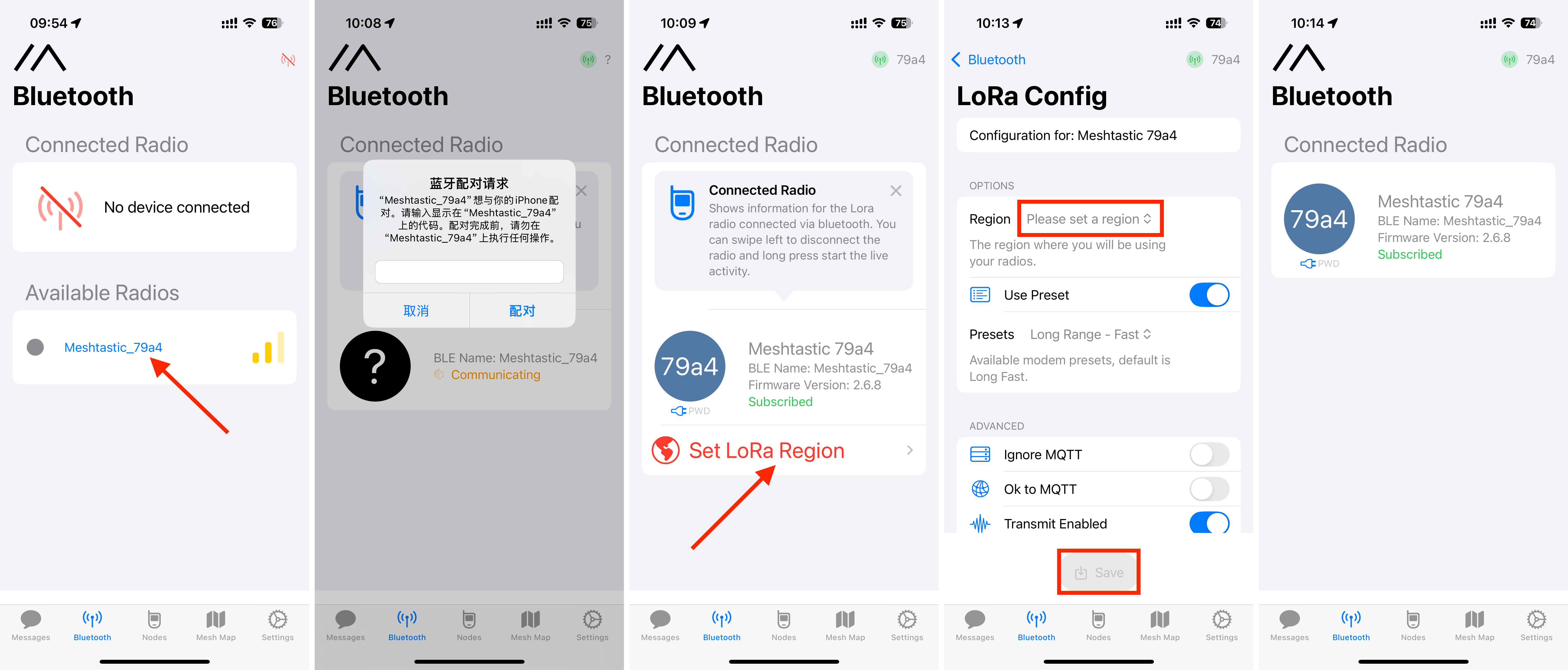
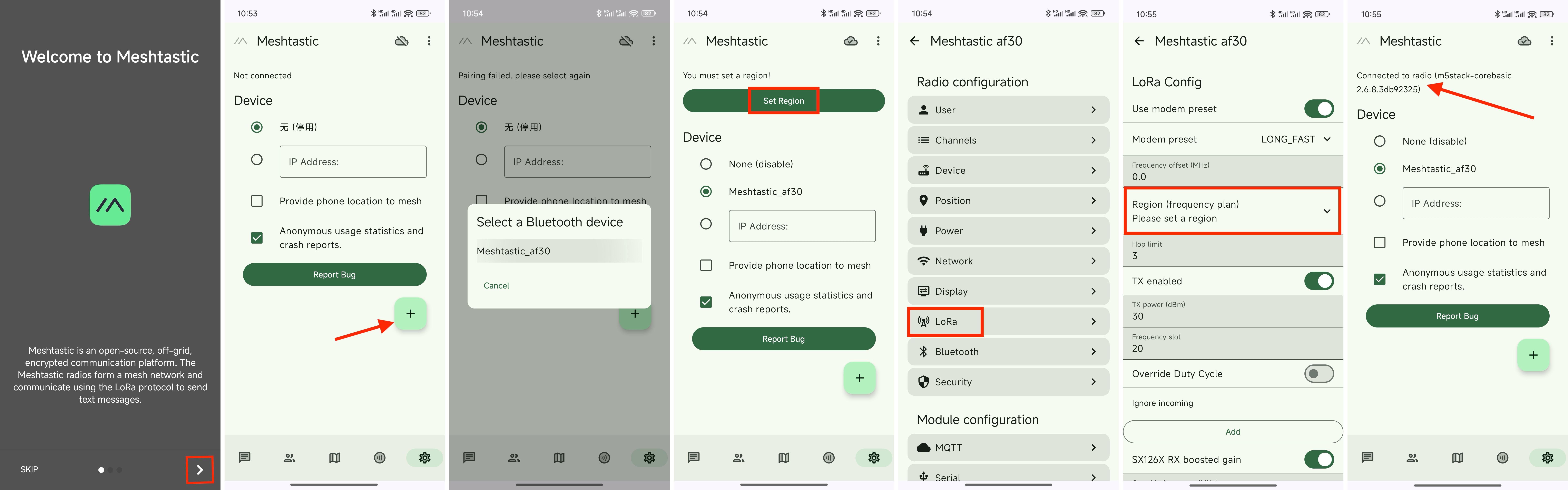
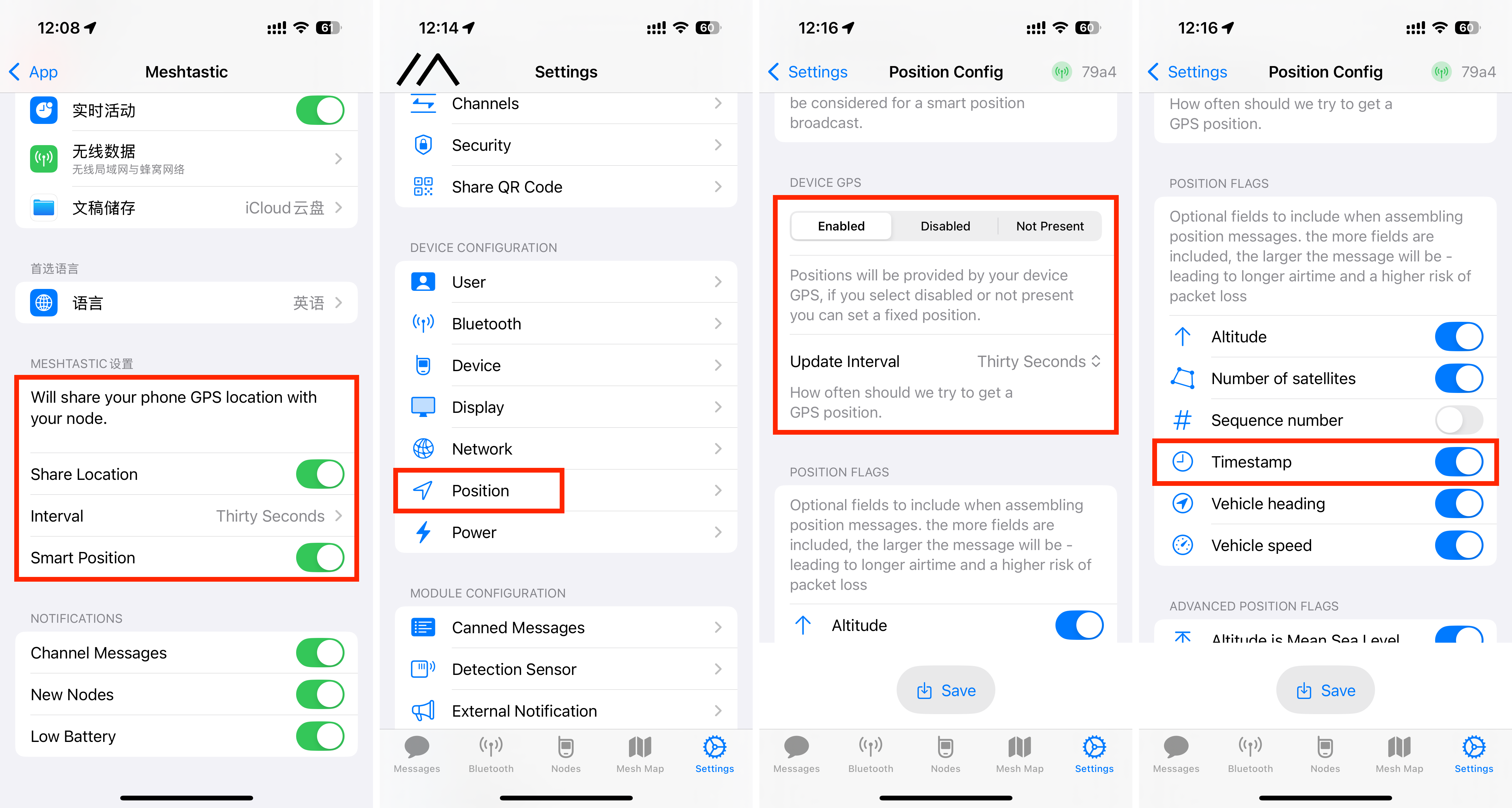
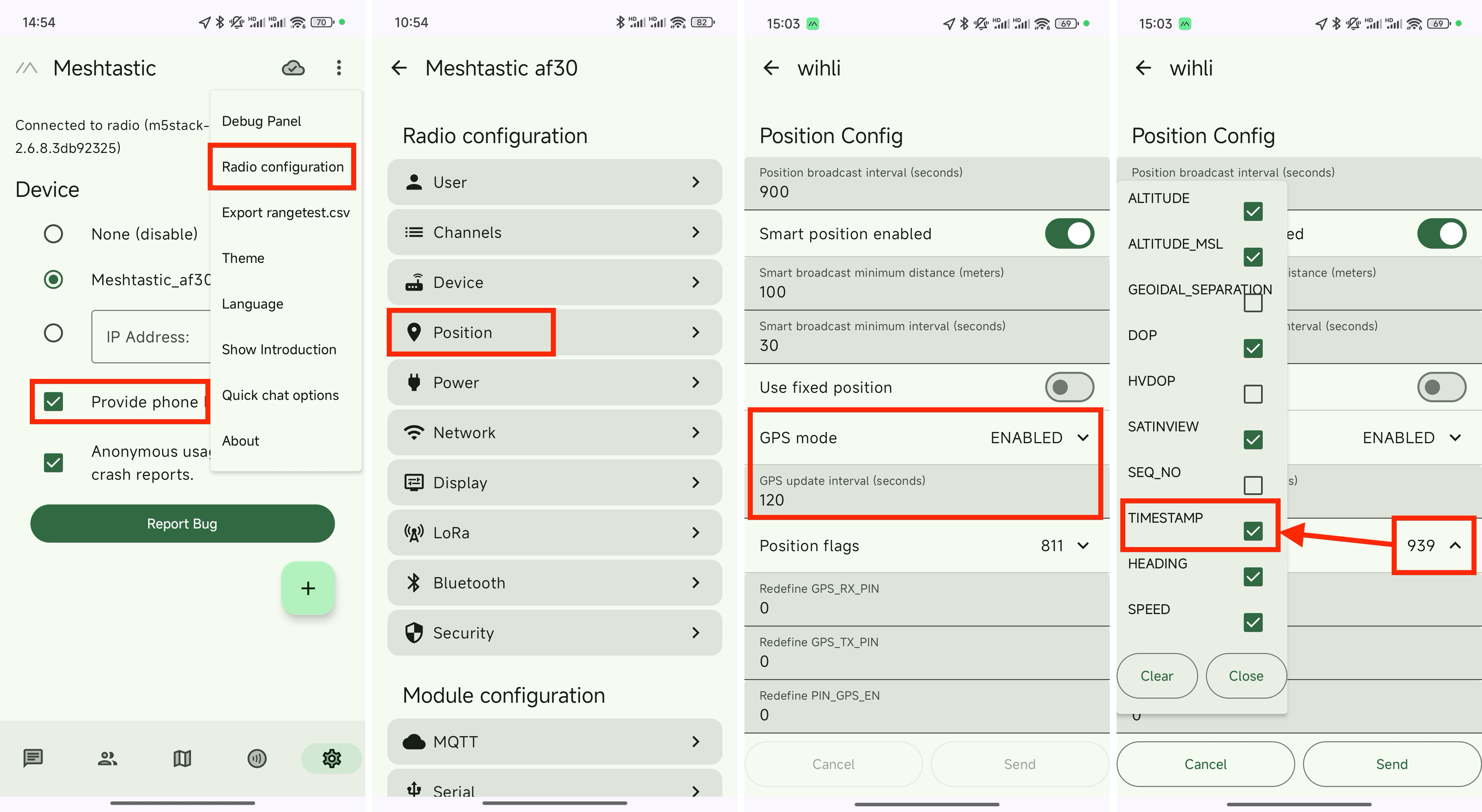
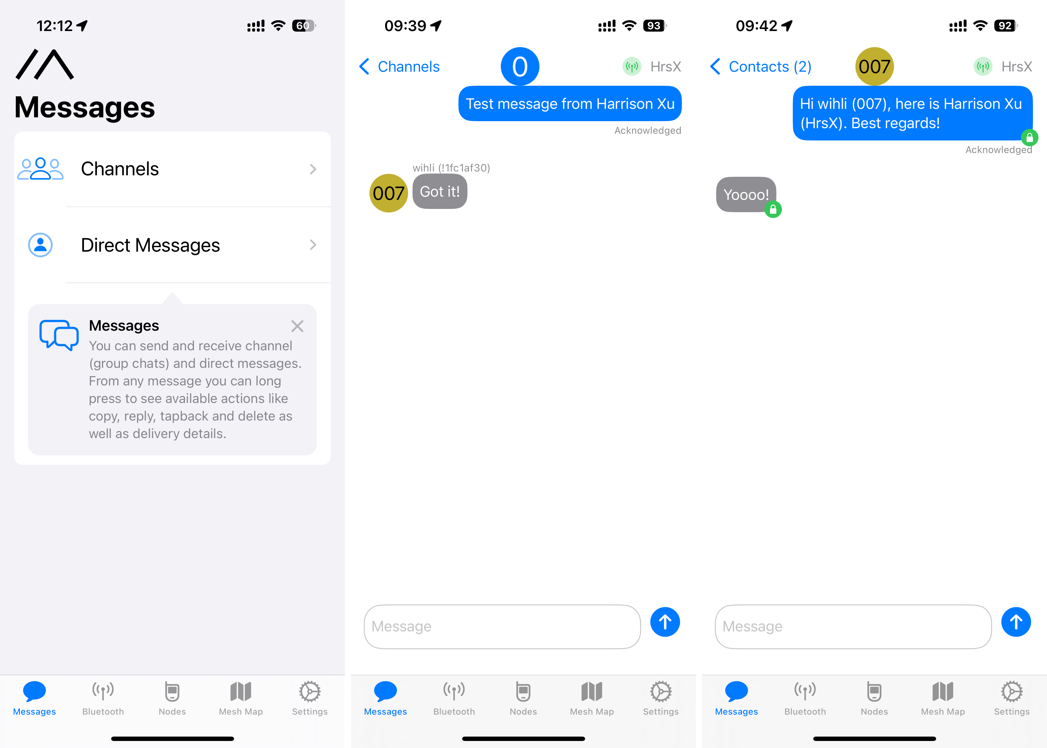
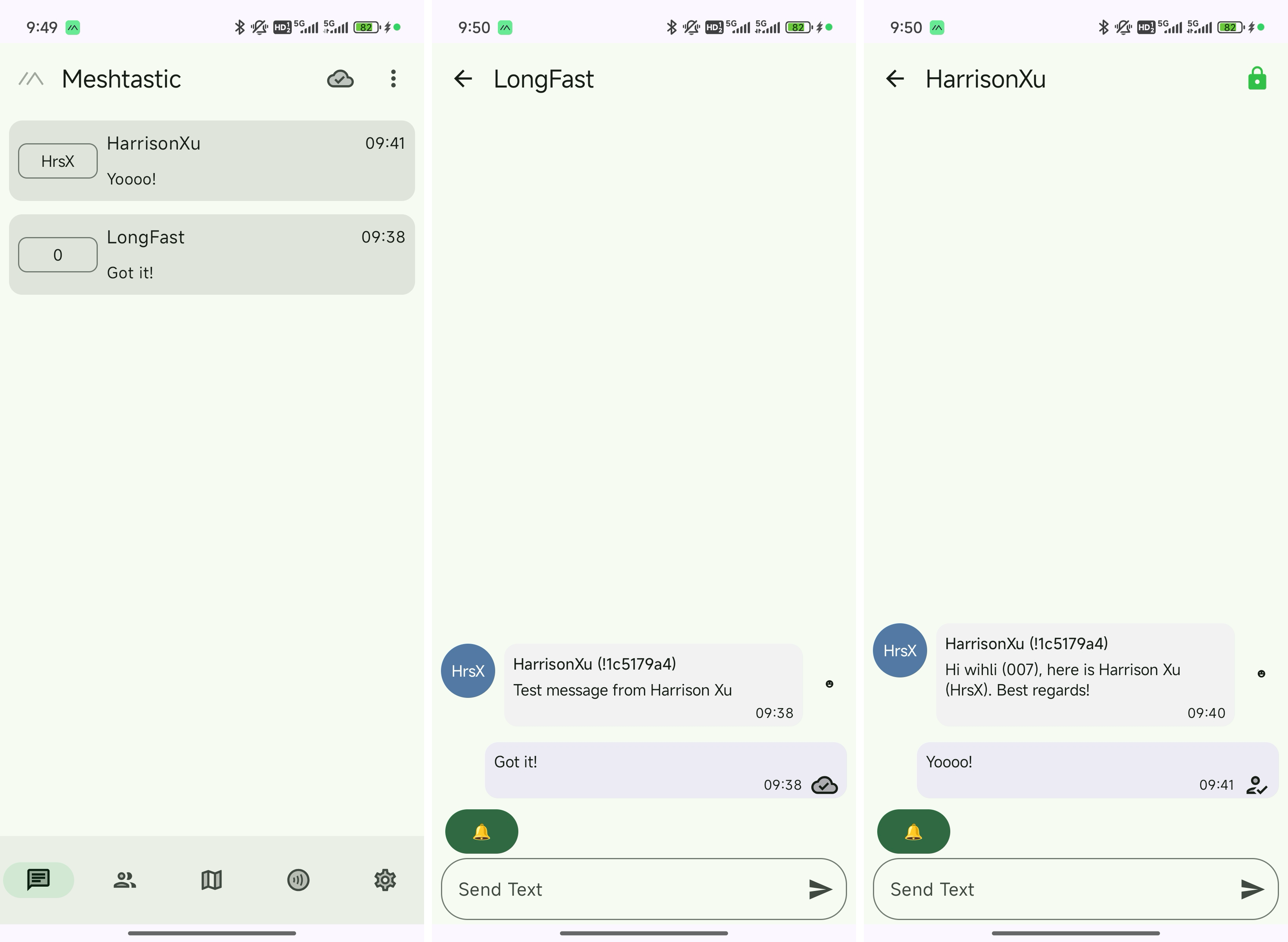
Several pre-configured examples are available via M5Burner, including community-driven projects. One highlight is Meshtastic for Cardputer-Adv, which integrates seamlessly with the Meshtastic mobile app for LoRa-based mesh networking and precise GPS mapping. The firmware provides a comprehensive menu for managing hardware segments like LoRa, GPS, and system time.
Conclusion
Additional examples include M5Launcher, which allows users to execute BIN files directly from the Micro-SD card. The factory demo provides a comprehensive hardware test. For those using the Arduino environment, extensive support is available via M5Stack libraries.
The Cardputer-Adv is exactly what its name suggests: a sophisticated, credit-card-sized computer with meaningful upgrades over the original. The CAP expansion module (e.g.,Cap LoRa-1262) is a powerful addition, and the new 2×7-pin header opens endless possibilities for hardware hackers.
When using M5Stack Modules or Bases, many users run into a common problem:
The same module, when stacked on different controllers (such as Basic, Core2, CoreS3, Tab5, etc.), uses different pin definitions. So, how should you correctly configure the pin numbers in your code?
If you have the same question, then understanding how the M5-Bus and DIP switches work is crucial.
This article will explain in a clear and practical way:
What is M5-Bus
Fixed Function Pins
What is a DIP Switch
By the end, you could have a much clearer idea of how to set the DIP switches on the module, and how to configure the corresponding pin numbers in your program.
1.What is M5-Bus
M5-Bus is a stack expansion bus design adopted by M5Stack stacking series products (Module, Base). The interface uses 2x15P@2.54mm pin headers/sockets. The Core series controllers can quickly stack different modules via the M5-Bus to achieve functional expansion. Its fixed positions define power pins such as GND, 5V, 3V3, and BAT, ensuring compatibility with various devices; other pins vary depending on the controller model, so you need to configure your program according to the actual pin mapping.
2.Fixed Function Pins
The pin numbers of M5-Bus are fixed starting from the GND pin at the top left corner, numbered from 1 to 30. This sequence is consistent across all controllers. The pins marked with a red box are fixed-function pins (power and GND, etc.), while other pins may have different functions or GPIO mappings depending on the main controller.
3.What is a DIP Switch
A DIP Switch is a toggle switch. It is used to flexibly change the connection of key module pins to adapt to different controller models. For example, in the case of Module GPS v2.0, there are three switchable pins: TXD, RXD, and PPS. Two onboard DIP switches control which pins these signals are connected to.
DIP Switch1’s switches 1–4 control TXD, switches 5–8 control RXD; DIP Switch2 is used to control PPS.
To avoid pin conflicts, typically each function pin only needs to be switched to one pin based on actual usage requirements. For example, in the following configuration, the 1st and 5th switches on DIP Switch1 are set to ON, the 2nd switch on DIP Switch2 is set to ON, and all other switches are set to OFF.
Based on the PCB silkscreen reference:
For Basic, the G17 pin; for Core2, the G14 pin; for CoreS3, the G17 pin will be connected to TXD.
For Basic, the G16 pin; for Core2, the G13 pin; for CoreS3, the G18 pin will be connected to RXD.
For Basic/Core2, the G35 pin; for CoreS3, the G10 pin will be connected to PPS.
When programming the device, you must modify the corresponding pin configuration according to the actual pin connections.
The DIP switch’s corresponding positions and numbering connected to the M5-Bus are fixed (indicated by blue box).
If the PCB silkscreen’s I/O reference table does not include the controller model you are currently using, you can refer to the existing device’s silkscreen PinMap to identify which M5-Bus pins the DIP switch connects to, and then map those to the corresponding pins of your current controller.
4.Quick Question Time
When using Module LoRa868 with Tab5, and the DIP switches are set as shown in the picture, which Tab5 pins are used for NSS, BUSY, RST, and IRQ, respectively?
Answer
5. Wrapping Up:
Treat the DIP Switch as a “Hardware-Level Remapping Tool”
A DIP switch essentially gives you a form of hardware-level pin remapping: The same module can be used with different Controllers, while routing key signals (TXD, RXD, PPS, etc.) to the most suitable GPIO pins.
In practice, if the module’s silkscreen or documentation already specifies how to set the DIP switches and which pins to use for your controller (for example, Core2, CoreS3), you can simply:
Set the DIP switches according to the instructions, and
Use the same pin numbers in your code as indicated in the documentation.
If your host controller is not listed, you can follow this simple procedure:
Check the module silkscreen/documentation Identify which function each DIP switch group corresponds to.
Refer to the Controller’s PinMap Find out which GPIO pins on your current Controller correspond to those M5-Bus pins.
Set the DIP switches Ensure that each functional signal is routed to exactly one target pin, avoiding conflicts or duplicate connections.
Update the pin definitions in your code Make sure the pins used for UART, interrupts, etc., match the GPIO pins you determined in the previous steps.
Once you understand this workflow, you no longer need to memorize which module “must be used with which Controller.” Instead, you can flexibly migrate and reuse modules across different controllers, according to your actual needs.
Understanding M5-Bus and DIP Switches: A Practical Guide for M5Stack Modules
With M5Stack CoreS3, you can seamlessly integrate advanced voice control into your Home Assistant ecosystem, enjoy real-time responsiveness, and experience true local AI interaction—secure, reliable, and fast.
The following guide walks you step-by-step through the process of setting up the CoreS3 HA Voice Assistant, from environment installation to voice activation.
4.After successfully installing the ESPHome addon, enable Show in sidebar in the ESPHome management page to add it to the left navigation bar.
🏷️Note
The compilation of firmware was based on ESPHome 2025.9.0/2025.10.0. If you face issue when compiling the project, consider switching to these versions.
2.Adding a Device
Open the ESPHome addon page and click NEW DEVICE in the lower-right corner to create a new device.
Click CONTINUE.
Select New Device Setup to create a new configuration file.
Give the configuration file a proper name.
Next, when selecting the device, cancel the Use recommended settings, then select ESP32-S3. Locate M5Stack CoreS3 among the list.
Copy the Home Assistant API Encryption Key for later use, then click Skip
3.Configuring the Device
Click EDIT in the lower-left corner of the device to modify the Wi-Fi connection configuration. (The Wi-Fi configuration defaults to the current HA server's Wi-Fi settings, but you can also modify it directly with plaintext: ssid:"xxxx")
Add the following package configuration link to add voice assistant functionality to the device.
Click SAVE and then INSTALL in the upper-right corner.
Select Manual Download to start compiling the firmware.
🏷️Firmware Compilation Note:
Compiling firmware through HA can be resource-intensive. The first compilation may take a long time for resource downloads, depending on the device hosting the HA service and network quality.
4.Firmware Flashing
Saving the Firmware
1.After firmware compilation is complete, click the Download button and select the Modern Format firmware to download to your local machine.
2 Use the ESPHome Web flashing tool to flash the firmware, or use tools like esptool. The starting address for firmware flashing is 0x00.
Connect the CoreS3 device to your computer via a USB-C cable and press and hold the reset button until the green light turns on, then release it to enter download mode.
In ESPHome Web, click Connect to connect to the device and select the corresponding device port.
Click INSTALL, upload the *.bin file previously compiled
Click INSTALL again to begin flashing
Wait until the flash is successful
5.Confirming the New Device Configuration
After firmware flashing, the device will automatically connect to Wi-Fi. The Home Assistant service within the same local network will prompt for a new device discovery. In Notifications, select the new device and click Check it out -> CONFIGURE, then follow the pop-up steps to add the device to the specified area to complete the configuration. If you do not receive a new device notification, click Settings -> Devices & services to view device status.
Then, you should be able to configure your Voice Assistant, or you can skip it and configure later
Test the wake word
Select an area
Select the pipeline
Finish the configuration
6.Waking Up the Device
After adding the device and completing the preparation steps for Home Assistant Cloud and Assist pipeline, you can now wake up the device using voice commands.
Demo video
With the steps above, your M5Stack CoreS3 has transformed into a fully functional Home Assistant voice terminal. Whether you use it to control lighting, monitor your environment, or communicate with other smart devices, CoreS3 bridges the gap between you and your smart home—bringing natural voice control to your fingertips.
M5Stack continues to empower developers with open, powerful, and beautifully designed hardware. With CoreS3, you’re not just installing firmware—you’re giving your smart home a voice.
From Hardware to Voice Intelligence: Building Your Own Home Assistant Voice Assistant with M5Stack CoreS3
In today’s rapidly advancing world of intelligent applications, image and video management is evolving at an unprecedented pace.
Imagine capturing breathtaking travel landscapes or precious moments of your child’s growth — and having your photos automatically categorized, tagged, and searchable via natural language. All processing happens locally, with no dependence on cloud servers, ensuring both speed and privacy. With the powerhouse performance of the M5Stack LLM‑8850 Card, bring your vision to life with an intelligent, deeply personalized photo album that’s uniquely yours.
M5StackLLM‑8850Card is an M.2 M‑Key2242AI accelerator card designed for edge devices. It is a powerful yet energy-efficient AI edge computing module, purpose-built for multi-modal large models, on-device inference, and intelligent analysis. It delivers high-performance inference for both language and vision models, and can be deployed effortlessly across diverse devices to enable offline, private AI services.
In this article, we’ll show you how to build an intelligent photo management platform with M5Stack LLM-8850 Card, making the organization of your pictures and videos smarter, faster, and more secure.
To achieve this, we’ll leverage Immich, an open‑source self‑hosted photo and video management platform that supports automatic backup, intelligent search, and cross‑device access.
cd immich
docker load -i ax-immich-server-aarch64.tar.gz
3. Prepare the working directory
unzip docker-deploy.zip
cp example.env .env
4.Start the container
docker compose -f docker-compose.yml -f docker-compose.override.yml up -d
If started successfully, the information is as follows:
m5stack@raspberrypi:~/rsp/immich $ docker compose -f docker-compose.yml -f docker-compose.override.yml up -d
WARN[0000] /home/m5stack/rsp/immich/docker-compose.override.yml: the attribute `version` is obsolete, it will be ignored, please remove it to avoid potential confusion
[+] Running 3/3
 ✔ Container immich_postgres  Started                                      1.0s
 ✔ Container immich_redis     Started                                      0.9s
 ✔ Container immich_server    Started                                      0.9s
5.Create a virtual environment
python -m venv mich
6.Activate the virtual environment
source mich/bin/activate
7.Install dependency packages
pip install https://github.com/AXERA-TECH/pyaxengine/releases/download/0.1.3.rc1/axengine-0.1.3-py3-none-any.whl
pip install -r requirements.txt
pip install immich_ml-1.129.0-py3-none-any.whl # Precompiled package may be upgraded; use the actual file name.
8.Start the immich_ml service
python -m immich_ml
After running, you should see:
(mich) m5stack@raspberrypi:~/rsp/immich $ python -m immich_ml
[10/10/25 09:50:12] INFO     Starting gunicorn 23.0.0
[10/10/25 09:50:12] INFO     Listening at: http://[::]:3003 (8698)
[10/10/25 09:50:12] INFO     Using worker: immich_ml.config.CustomUvicornWorker
[10/10/25 09:50:12] INFO     Booting worker with pid: 8699
2025-10-10 09:50:13.589360675 [W:onnxruntime:Default, device_discovery.cc:164 DiscoverDevicesForPlatform] GPU device discovery failed: device_discovery.cc:89 ReadFileContents Failed to open file: "/sys/class/drm/card1/device/vendor"
[INFO] Available providers:  ['AXCLRTExecutionProvider']
/home/m5stack/rsp/immich/mich/lib/python3.11/site-packages/immich_ml/models/clip/cn_vocab.txt
[10/10/25 09:50:16] INFO     Started server process [8699]
[10/10/25 09:50:16] INFO     Waiting for application startup.
[10/10/25 09:50:16] INFO     Created in-memory cache with unloading after 300s
                             of inactivity.
[10/10/25 09:50:16] INFO     Initialized request thread pool with 4 threads.
[10/10/25 09:50:16] INFO     Application startup complete.
In your browser, enter the Raspberry Pi IP address and port 3003, for example: 192.168.20.27:3003
Note: The first visit requires registering an administrator account; the account and password are saved locally.
Once configured, you can upload images.
The first time, you need to configure the machine learning server. Refer to the diagram below to enter the configuration.
Set the URL to the Raspberry Pi IP address and port 3003, e.g., 192.168.20.27:3003.
If using Chinese search for the CLIP model, set it to ViT-L-14-336-CN__axera; for English search, set it to ViT-L-14-336__axera.
After setup, save the configuration.
The first time, you need to manually go to the Jobs tab and trigger SMART SEARCH.
Enter the description of the image in the search bar to retrieve relevant images.
Through this hands-on project, we’ve not only built a powerful smart photo album platform, but also experienced the exceptional performance of the M5Stack LLM‑8850 Card in edge AI computing. Whether setting up a private photo album on your Raspberry Pi or deploying intelligent image processing in security scenarios, the M5Stack LLM‑8850 Card delivers efficient, stable computing power you can rely on.
It brings AI closer to where your data resides, enabling faster, more secure processing and turning your ideas into reality. If you’re looking for a solution for on-device AI inference, give M5Stack LLM‑8850 Card a try — it might just become the core engine of your next project.
1.Manually download the program and upload it to raspberrypi5, or pull the model repository with the following command.
cd immich
docker load -i ax-immich-server-aarch64.tar.gz
3. Prepare the working directory
unzip docker-deploy.zip
cp example.env .env
4.Start the container
docker compose -f docker-compose.yml -f docker-compose.override.yml up -d
If started successfully, the information is as follows:
m5stack@raspberrypi:~/rsp/immich $ docker compose -f docker-compose.yml -f docker-compose.override.yml up -d
WARN[0000] /home/m5stack/rsp/immich/docker-compose.override.yml: the attribute `version` is obsolete, it will be ignored, please remove it to avoid potential confusion
[+] Running 3/3
 ✔ Container immich_postgres  Started                                      1.0s
 ✔ Container immich_redis     Started                                      0.9s
 ✔ Container immich_server    Started                                      0.9s
5.Create a virtual environment
python -m venv mich
6.Activate the virtual environment
source mich/bin/activate
7.Install dependency packages
pip install https://github.com/AXERA-TECH/pyaxengine/releases/download/0.1.3.rc1/axengine-0.1.3-py3-none-any.whl
pip install -r requirements.txt
pip install immich_ml-1.129.0-py3-none-any.whl # Precompiled package may be upgraded; use the actual file name.
8.Start the immich_ml service
python -m immich_ml
After running, you should see:
(mich) m5stack@raspberrypi:~/rsp/immich $ python -m immich_ml
[10/10/25 09:50:12] INFO     Starting gunicorn 23.0.0
[10/10/25 09:50:12] INFO     Listening at: http://[::]:3003 (8698)
[10/10/25 09:50:12] INFO     Using worker: immich_ml.config.CustomUvicornWorker
[10/10/25 09:50:12] INFO     Booting worker with pid: 8699
2025-10-10 09:50:13.589360675 [W:onnxruntime:Default, device_discovery.cc:164 DiscoverDevicesForPlatform] GPU device discovery failed: device_discovery.cc:89 ReadFileContents Failed to open file: "/sys/class/drm/card1/device/vendor"
[INFO] Available providers:  ['AXCLRTExecutionProvider']
/home/m5stack/rsp/immich/mich/lib/python3.11/site-packages/immich_ml/models/clip/cn_vocab.txt
[10/10/25 09:50:16] INFO     Started server process [8699]
[10/10/25 09:50:16] INFO     Waiting for application startup.
[10/10/25 09:50:16] INFO     Created in-memory cache with unloading after 300s
                             of inactivity.
[10/10/25 09:50:16] INFO     Initialized request thread pool with 4 threads.
[10/10/25 09:50:16] INFO     Application startup complete.
In your browser, enter the Raspberry Pi IP address and port 3003, for example: 192.168.20.27:3003
Note: The first visit requires registering an administrator account; the account and password are saved locally.
Once configured, you can upload images.
The first time, you need to configure the machine learning server. Refer to the diagram below to enter the configuration.
Set the URL to the Raspberry Pi IP address and port 3003, e.g., 192.168.20.27:3003.
If using Chinese search for the CLIP model, set it to ViT-L-14-336-CN__axera; for English search, set it to ViT-L-14-336__axera.
After setup, save the configuration.
The first time, you need to manually go to the Jobs tab and trigger SMART SEARCH.
Enter the description of the image in the search bar to retrieve relevant images.
Through this hands-on project, we’ve not only built a powerful smart photo album platform, but also experienced the exceptional performance of the M5Stack LLM‑8850 Card in edge AI computing. Whether setting up a private photo album on your Raspberry Pi or deploying intelligent image processing in security scenarios, the M5Stack LLM‑8850 Card delivers efficient, stable computing power you can rely on.
It brings AI closer to where your data resides, enabling faster, more secure processing and turning your ideas into reality. If you’re looking for a solution for on-device AI inference, give M5Stack LLM‑8850 Card a try — it might just become the core engine of your next project.
-->
LLM‑8850 Card in Action: Creating an AI‑Powered Photo Management Platform with Immich
A LoRa node that collects and sends information (e.g., a connected sensor). In this case, we're going to use a board with the integrated SX1276 chip (which would also be a valid device to act as a LoRa gateway).
A USB cable to power the DATA board ( with a charging cable, you will not be able to install the software).
Something important to keep in mind is that the LoRa module has some small switches on the back ('DIP switches') that modify the pin assignment, and logically, it must match what we indicate in the ESPHome code.
To do this, make sure the switches are in the following position (2, 6 and 7 on and the rest off).
From here, the process will be similar for any compatible motherboard (adapting the steps and connection diagram to the specifications of your device). The steps we followed are as follows:
6.Click “Save” and “Install.” Select “Manual download” and wait for the code to compile.
7.When finished, select the “Modern format” option to download the corresponding '.bin' file.
8.Connect the M5Stack Core S3 SE to your computer using the USB-C data cable via the port on the side.
9.Now go to the ESPHome page and click "Connect." In the pop-up window, select your board and click "Connect."
10.Now click on “Install” and select the '.bin' file obtained in step 7. Again, click on “Install”.
11.Return to Home Assistant and go to Settings > Devices & Services. Your device should have been discovered and appear at the top, waiting for you to press the "Configure" button. Otherwise, click the "Add integration" button, search for "ESPHome," and enter your board's IP address in the "Host" field. As always, we recommend assigning a static IP address to your router to avoid future issues if it changes.
LoRa node configuration
Now that we have our LoRa gateway, let's configure a node to send information to it. To do this, we'll follow steps very similar to those in the previous section:
6.Note that the pin assignment is different (because we're using a different device than the one we used for the Gateway), but the rest of the configuration is exactly the same as in the previous section. This is important so they can communicate with each other.
7.Click “Save” and “Install.” Select “Manual download” and wait for the code to compile.
8.When finished, select the “Modern format” option to download the corresponding '.bin' file.
9.Connect the board to your computer using the Micro USB data cable through the port on the side.
10.Now go to the ESPHome page and click "Connect." In the pop-up window, select your board and click "Connect."
11.Now click on “Install” and select the '.bin' file obtained in step 8. Again, click on “Install”.
12.Return to Home Assistant and go to Settings > Devices & Services . Your device should have been discovered and appear at the top, waiting for you to press the "Configure" button . Otherwise, click the "Add integration" button, search for "ESPHome," and enter your board's IP address in the "Host" field. As always, we recommend assigning a static IP address to your router to avoid future issues if it changes.
Check the communication
Let's do a little test to check that both devices are communicating correctly (the Gateway and the node) .
1.Make sure both devices are turned on and are online in Home Assistant and ESPHome.
2.From Home Assistant, go to Settings > Devices & Services > ESPHome and access one of them (for example, the Gateway).
3.Open a new window (without closing the previous one), enter the ESPHome plugin and access the logs of the other device (in this case, the node).
4.In the Home Assistant window, click the "Transmit Packet" button. You'll immediately see the logs from the second device recording the incoming packet.
You can perform a reverse test to verify that communication is working both ways. If everything went well, your devices are now communicating.
Sending information
Logically, the point of integrating LoRa into Home Assistant is to send some kind of useful information (such as the value of a sensor connected to the node).
1.The first step is to add the sensor you're interested in to the node board. For example, we're going to add a PIR sensor to get the long-awaited motion sensor on the mailbox. To do this, we've added the following code snippet:
2.If you look at the code above, it's the same one we would use in any "normal" scenario. However, to send the information to our LoRa Gateway, we need to add something extra using the 'Packet Transport' component.
3.Analyze the code above and observe the following:
·In the 'encryption' attribute, you have to indicate the encryption key for your message (whatever you want), so that it cannot be received by anyone on the same frequency.
·We've identified the ID of the sensor we want to send (in this case, the binary sensor with the ID "pir_sensor") . You can add any other sensors you're interested in here.
4.Now we are going to add the following to the code of our LoRa Gateway, so that it receives the information.
5.Now we’re going to add the following to the code of our LoRa Gateway, so it can receive the information.
Again, analyze the code and note the following:
lWe have specified the ESPHome device name of our LoRa node as the data provider.
lIn the ‘encryption’ attribute, we have indicated exactly the same key as in the node.
lTo transform the information received into a gateway sensor, we used the “packet_transport” platform. We assigned it an “id” (you can choose any) and again indicated the LoRa node name as the provider. This is an internal ESPHome sensor.
lTo display this information in Home Assistant, we created a template sensor of the same type, assigning it the value of the internal sensor created in the previous step.
6.And that's it! If you now check your gateway device in Home Assistant, you’ll see that it already shows the information from the node.
Customize your Gateway
Since we used the M5Stack Core S3 SE to integrate LoRa into Home Assistant, we can take advantage of its other features to customize it! Below, we're leaving you the full code to create a screen that notifies you when you receive letters in your mailbox!
LoRa (an acronym for "Long Range") is a radio frequency communication protocol that enables long-distance data transmission (up to 10 km in open fields) with very low power consumption. Therefore, it offers two major advantages:
It has a much greater range than the protocols we commonly use (WiFi, Bluetooth, Zigbee, etc.). This makes it the ideal choice for remote sensors (storage rooms, mailboxes, large gardens, etc.).
It doesn't rely on the telephone or electrical network to transmit information, so different LoRa devices can communicate even during a power outage.
However, it also has its limitations, as its data transfer speed is slow. In practice, this means it's perfect for sending simple data (commands to our devices, numbers, or text strings), but it's not a suitable protocol for transmitting photos or videos.
Additionally, you should consider the frequency LoRa uses in your geographic area. For example, in Europe it's 868 MHz, while in the US and most of Latin America it's 915 MHz.
Prerequisites
To integrate LoRa into Home Assistant, you will need the following components:
A LoRa gateway that receives information from the various nodes and transmits it to Home Assistant. In this case, we're going to create a gateway with the M5Stack Core S3 SE(yes, the same one we already usedto Activate Assist ), combined with the LoRa868 modules and an external battery(this is optional).
A LoRa node that collects and sends information (e.g., a connected sensor). In this case, we're going to use a board with the integrated SX1276 chip (which would also be a valid device to act as a LoRa gateway).
A USB cable to power the DATA board ( with a charging cable, you will not be able to install the software).
Something important to keep in mind is that the LoRa module has some small switches on the back ('DIP switches') that modify the pin assignment, and logically, it must match what we indicate in the ESPHome code.
To do this, make sure the switches are in the following position (2, 6 and 7 on and the rest off).
From here, the process will be similar for any compatible motherboard (adapting the steps and connection diagram to the specifications of your device). The steps we followed are as follows:
6.Click “Save” and “Install.” Select “Manual download” and wait for the code to compile.
7.When finished, select the “Modern format” option to download the corresponding '.bin' file.
8.Connect the M5Stack Core S3 SE to your computer using the USB-C data cable via the port on the side.
9.Now go to the ESPHome page and click "Connect." In the pop-up window, select your board and click "Connect."
10.Now click on “Install” and select the '.bin' file obtained in step 7. Again, click on “Install”.
11.Return to Home Assistant and go to Settings > Devices & Services. Your device should have been discovered and appear at the top, waiting for you to press the "Configure" button. Otherwise, click the "Add integration" button, search for "ESPHome," and enter your board's IP address in the "Host" field. As always, we recommend assigning a static IP address to your router to avoid future issues if it changes.
LoRa node configuration
Now that we have our LoRa gateway, let's configure a node to send information to it. To do this, we'll follow steps very similar to those in the previous section:
6.Note that the pin assignment is different (because we're using a different device than the one we used for the Gateway), but the rest of the configuration is exactly the same as in the previous section. This is important so they can communicate with each other.
7.Click “Save” and “Install.” Select “Manual download” and wait for the code to compile.
8.When finished, select the “Modern format” option to download the corresponding '.bin' file.
9.Connect the board to your computer using the Micro USB data cable through the port on the side.
10.Now go to the ESPHome page and click "Connect." In the pop-up window, select your board and click "Connect."
11.Now click on “Install” and select the '.bin' file obtained in step 8. Again, click on “Install”.
12.Return to Home Assistant and go to Settings > Devices & Services . Your device should have been discovered and appear at the top, waiting for you to press the "Configure" button . Otherwise, click the "Add integration" button, search for "ESPHome," and enter your board's IP address in the "Host" field. As always, we recommend assigning a static IP address to your router to avoid future issues if it changes.
Check the communication
Let's do a little test to check that both devices are communicating correctly (the Gateway and the node) .
1.Make sure both devices are turned on and are online in Home Assistant and ESPHome.
2.From Home Assistant, go to Settings > Devices & Services > ESPHome and access one of them (for example, the Gateway).
3.Open a new window (without closing the previous one), enter the ESPHome plugin and access the logs of the other device (in this case, the node).
4.In the Home Assistant window, click the "Transmit Packet" button. You'll immediately see the logs from the second device recording the incoming packet.
You can perform a reverse test to verify that communication is working both ways. If everything went well, your devices are now communicating.
Sending information
Logically, the point of integrating LoRa into Home Assistant is to send some kind of useful information (such as the value of a sensor connected to the node).
1.The first step is to add the sensor you're interested in to the node board. For example, we're going to add a PIR sensor to get the long-awaited motion sensor on the mailbox. To do this, we've added the following code snippet:
2.If you look at the code above, it's the same one we would use in any "normal" scenario. However, to send the information to our LoRa Gateway, we need to add something extra using the 'Packet Transport' component.
3.Analyze the code above and observe the following:
·In the 'encryption' attribute, you have to indicate the encryption key for your message (whatever you want), so that it cannot be received by anyone on the same frequency.
·We've identified the ID of the sensor we want to send (in this case, the binary sensor with the ID "pir_sensor") . You can add any other sensors you're interested in here.
4.Now we are going to add the following to the code of our LoRa Gateway, so that it receives the information.
5.Now we’re going to add the following to the code of our LoRa Gateway, so it can receive the information.
Again, analyze the code and note the following:
lWe have specified the ESPHome device name of our LoRa node as the data provider.
lIn the ‘encryption’ attribute, we have indicated exactly the same key as in the node.
lTo transform the information received into a gateway sensor, we used the “packet_transport” platform. We assigned it an “id” (you can choose any) and again indicated the LoRa node name as the provider. This is an internal ESPHome sensor.
lTo display this information in Home Assistant, we created a template sensor of the same type, assigning it the value of the internal sensor created in the previous step.
6.And that's it! If you now check your gateway device in Home Assistant, you’ll see that it already shows the information from the node.
Customize your Gateway
Since we used the M5Stack Core S3 SE to integrate LoRa into Home Assistant, we can take advantage of its other features to customize it! Below, we're leaving you the full code to create a screen that notifies you when you receive letters in your mailbox!
Build a Long‑Range LoRa Gateway for Home Assistant with M5Stack
In today's fast-evolving IoT and smart hardware landscape, a smooth and responsive user interface (UI) has become just as important as core functionality.
M5Stack, continuing to refine its visual programming platform UIFlow2, now officially integrates the powerful LVGL (Light and Versatile Graphics Library) — giving makers and developers the best of both worlds: the speed of visual programming and the freedom of a professional embedded GUI framework.
Why LVGL?
UIFlow2, built on MicroPython, is designed to lower the barrier for hardware programming. Earlier versions included basic controls and drawing functions — useful for simple projects but less suited for complex UI needs.
LVGL changes the game. It's an open-source, lightweight, cross-platform embedded GUI library with:
Rich widget library: Buttons, sliders, progress bars, charts, and more
High-performance rendering: Adaptable to different display memory sizes and refresh rates
Flexible extensibility: Animations, themes, event callbacks, and advanced custom styling
With UIFlow2's LVGL integration, developers can start by dragging and dropping blocks, then fine-tune behavior via Python code — moving seamlessly from beginner-friendly to pro-level control.
What's Available Now
UIFlow2 already supports LVGL in its first integration phase:
After downloading the program to the device, controls will immediately display on the screen and support real-time interaction.
What's Coming Next
We're pushing towards full LVGL integration and a more intuitive design experience:
More widget support: Charts, animations, themes, advanced style management
Improved visual designer: What You See Is What You Get layout editing (WYSIWYG)
Wider hardware coverage: More display modules and input peripherals like Module Display and Unit CardKB
Ultimately, UIFLow2+LVGL bridges the gap between quick, beginner-friendly prototyping and precise, professional-grade UI development — giving every creator the speed to start and the depth to go further.
UIFlow2 Officially Supports LVGL: Enabling Greater Flexibility in Hardware UI Development
Before we begin, make sure you have Home Assistant installed. You can follow the official documentation for your preferred platform.
Once Home Assistant is up and running:
Go to Settings → Add-ons → Add-on Store
Search for and install the ESPHome add-on
After installation, enable Show in sidebar for quick access
2. Adding the Device
1.Open the ESPHome sidebar and click NEW DEVICE in the lower right corner.
2.Click CONTINUE when the setup screen appears.
3.Name your device (e.g., Atom-Lite), then proceed.
4.On the device type screen:
oUncheck Use recommended settings
oSelect ESP32 → choose M5Stack-ATOM
5.Click NEXT and copy the encryption key that appears.
6.Choose Manual download to begin compiling the firmware.
3. Firmware Setup & Compilation
Back on the ESPHome dashboard, you’ll now see your new Atom-Lite device listed.
1.Click EDIT to open the YAML configuration editor
2.Replace the content with the following configuration (update your Wi-Fi credentials!):
esphome:
  name: atom-lite
  friendly_name: Atom-Lite

esp32:
  board: m5stack-atom
  framework:
    type: arduino

logger:
api:
  encryption:
    key: "*********"

ota:
  - platform: esphome
    password: "*****************"

wifi:
  ssid: "*********"
  password: "***********"
  ap:
    ssid: "Atom-Lite Fallback Hotspot"
    password: "jFsIc2XGuKRe"

captive_portal:

binary_sensor:
  - platform: gpio
    pin:
      number: GPIO39
      mode: INPUT
      inverted: true
    name: "Atom Button"
    id: atom_button
    filters:
      - delayed_on: 50ms
      - delayed_off: 50ms
    on_multi_click:
      - timing:
          - ON for at most 0.8s
          - OFF for at most 0.5s
          - ON for at most 0.8s
          - OFF for at least 0.2s
        then:
          - logger.log: "Double Clicked"
          - light.turn_on:
              id: atom_light
              red: 100%
              blue: 50%
              green: 20%
              brightness: 50%
      - timing:
          - ON for at least 0.8s
        then:
          - logger.log: "Single Long Clicked"
          - light.turn_on:
              id: atom_light
              green: 100%
              blue: 50%
              red: 30%
              brightness: 100%

light:
  - platform: neopixelbus
    type: GRB
    pin: GPIO27
    num_leds: 1
    variant: sk6812
    name: "Atom RGB Light"
    id: atom_light
    restore_mode: RESTORE_DEFAULT_OFF
    effects:
      - random:
          name: "Random"
          transition_length: 1s
          update_interval: 1s
3.Click SAVE, then INSTALL → Manual download to compile
Note: The first compilation may take several minutes, depending on your setup and network.
4. Flash the Firmware to M5Atom Lite
After compiling the firmware:
1.Click DOWNLOAD, and choose Factory format
2.Connect the M5Atom Lite to your computer using a USB-C data cable
3.Back in ESPHome, select INSTALL → Plug into this computer
4.Click Open ESPHome Web
5.Press CONNECT, then select the detected serial port
6.Click INSTALL and wait for the firmware installation to complete.
Once flashing is complete, the device will restart and attempt to connect to your Wi-Fi.
5. Add the Device to Home Assistant
Once Atom Lite is online:
1.Open Settings → Integrations in Home Assistant
2.Under Discovered, click ADD and follow the prompts to integrate it
6. Create an Automation
You can now set up a basic automation using the button to control the light:
1.In the Home Assistant page, go to Settings → Device& Service
2.Locate ESPHome → hit Atom-Lite → clickAutomations
3.Select Create new automation→ ADD TRIGGER → Entity → State → Atom Button
4.In the When section, change the status from Off to On
5.In the Then do section, select ADD ACTION → Light → Toggle → + Choose entity → Atom-Lite RGB Light → Save
This simple setup turns the button into a light switch for the RGB LED.
7. Add Atom RGB Light to Your Dashboard
To control the RGB light from the Home Assistant interface:
1.Go to Overview → Edit
2.In the By card page, input Light on the search cards Select the Light card type
3.Choose the Atom RGB Light entity
4.Save the changes
The light can now be toggled and color-adjusted directly from the dashboard.
8. Demo & Behavior
Here’s how your new Atom-Lite smart RGB light behaves:
Single Click → RGB light toggles pink
Long Press (2+ seconds) → RGB light switches to green
Light state updates in real-time and can also be controlled via the Home Assistant dashboard
Conclusion
Home Assistant makes smart home control simple, with M5Stack Atom-Lite and ESPHome, setting up RGB lighting is just the start. With the same process, you can go further by adding mode device like a human presence sensor to detect movement, turn on lights automatically, or turn on the AC and set it to the optimal temperature when someone enters the room.
Integrating M5Atom Lite into Home Assistant Using ESPHome
M5StampS3 board, a microcontroller based on the ESP32-S3.
1.28-inch circular TFT touchscreen display.
Rotary encoder surrounding the screen, with a push button at the bottom.
RFID and card reader (13.56MHz), although I find it to be not very precise.
Buzzer for sound output.
Battery connection port with built-in charging circuitry.
Two expansion ports for I2C and GPIO.
All these features packed into a single, ready-to-use device which make the M5Dial a truly compelling gadget. And since it's powered by an ESP32-S3, we can easily integrate it into Home Assistant using ESPHome.
Mr. Avocado
As usual, we wanted to make the most of these features by building a fun and practical project. This time, it's something special — a device co-designed with our Patreon community.
We named it Mr. Avocado, a playful nod to the iconic “Mr. Potato.” The goal was to create a multifunctional device with the following capabilities:
Lock screen that shows the current date and time after a few seconds of inactivity
Automatic screen-off to save power
A streamlined interface to control up to 8 devices
Alarm clock with a custom ringtone, configurable via Home Assistant
NFC/RFID reader for tags and cards
And thanks to the ESP32-S3, it can also act as a Bluetooth Proxy to serve as a presence sensor with Bermuda.
Prerequisites
To integrate the M5Dial into Home Assistant, you’ll need:
⚠️ While we’ve managed to implement all these features for Mr. Avocado, my recommendation is to comment out (or remove) any parts of the code you’re not planning to use. This will help improve the device’s performance and prevent it from freezing.
6.This code does not include the credentials needed for your device to connect to your Wi-Fi network and your Home Assistant instance. You’ll need to add them manually. Specifically, I’m referring to the following lines from the code you copied in Step 4.
# Enable Home Assistant API
api:
  encryption:
    key: "bg6hash6sjdjsdjk02hh0qnQeYVwm123vdfKE8BP5"

ota:
  - platform: esphome
    password: "asddasda27aab65a48484502b332f"

wifi:
  ssid: !secret wifi_ssid
  password: !secret wifi_password

  # Enable fallback hotspot (captive portal) in case wifi connection fails
  ap:
    ssid: "Assist Fallback Hotspot"
    password: "ZsasdasdHGP2234"
7.What you need to do is to find the corresponding lines in the code (they’re at the top) and add your Wi-Fi and Home Assistant credentials there.
8.Now, click “Save” and then “Install.” Choose “Manual download” and wait for the code to compile.
9.Once the compilation is complete, select the “Modern format” option to download the corresponding .bin file.
10.Connect the M5Stack Dial to your computer using a USB-C data cable via the port on the bottom of the device.
11.Next, go to the ESPHome web page and click “Connect.” In the popup window, select your board and click “Connect.”
12.Then click “Install” again and choose the .bin file you downloaded in step 9. Click “Install” once more to flash the firmware.
13.Return to Home Assistant and go to Settings > Devices & Services. In most cases, your device should be automatically discovered and appear at the top, waiting for you to click “Configure.” If not, click “Add Integration,” search for “ESPHome,” and enter your board’s IP address in the Host field. As always, it’s a good idea to assign astatic IP to your device in your router settings to avoid connection issues later on.
14.To finish, go to Settings > Devices & Services > ESPHome, click the “Configure” link next to your device, and in the popup window, check the box that says, “Allow this device to make Home Assistant API calls,” then click “Submit.” This will allow us to control devices directly from the screen.
Device Customization
Alright, you’ve successfully integrated the M5Stack Dial into Home Assistant as Mr. Avocado. Now let’s go over how to take full advantage of its features.
Screensaver Control
To protect the screen, we’ve added a customizable screensaver function. You can easily tweak it by accessing the entities exposed by the device in Home Assistant. Pay special attention to these three controls.
After a few seconds of inactivity (you can set the duration using the “Screen Saver” slider), the menu automatically hides, showing the clock and date with reduced screen brightness. Additionally, if you enable “Auto Lock,” the screen will turn off completely a few seconds later (adjustable using the “Auto Lock” slider).
Customize the Wallpaper
Of course, you can use our default Mr. Avocado background images — or replace them with your own. Just update the image references in the first few lines of the code to point to your preferred files.
You can also customize which devices you want to control and the icons that represent them. Throughout the code, you’ll find examples for controlling different types of entities—lights, climate, vacuum, switches, humidifiers, and more. But if you understand the logic, you can control any Home Assistant device!
The example menu is optimized for 8 devices, but you can add more icons or even paginate the menu. Plus, if you press on any device, you’ll see advanced controls using the rotary encoder.
Sounds and Alarm Clock
Since Mr. Avocado has a built-in buzzer, you can use it as an alarm or timer, making it sound whenever you want. Just use the “Alarm” button entity exposed by the device. You can also enable or disable a beep sound when navigating through the menu.
By the way, you can customize the alarm tone, as I explained in this article.
Mr. Avocado also includes an NFC/RFID reader, although it’s not its strongest feature — I find the tag detection to be somewhat imprecise. Still, if you want to use it, be sure to check out this article where I explain in detail how to create automations for each specific tag.
Mr. Avocado Stand
By the way, if you like it, you can also get our custom Mr. Avocado stand!
Thanks to the threaded mount built into the M5Stack Dial, attaching it is very easy. Just screw the device onto the stand’s base and route the USB-C power cable through the rear opening. I recommend using a 90º angled USB-C cable to make positioning easier (although you can also rotate the screen to your liking).
Also, keep in mind the case has space at the top and an opening at the bottom—both intentionally designed so you can access the two expansion ports (I2C and GPIO) to add your favorite sensors.
⭐ If you have a 3D printer, you can download this stand I designed from our Patreon profile. If not, you can also purchase it from La R3D and have it shipped to your home!
How to Integrate the M5Stack Dial with Home Assistant (Full ESPHome Guide)
Launched in October 2023 by M5Stack, the StickC Plus2 has quickly become a popular choice among makers, educators, and embedded system developers. It’s widely used in IoT projects, embedded systems, and cybersecurity applications. Many users even compare it with Flipper Zero as affordable alternatives for their similar roles in wireless testing and cybersecurity tools.
In this article, we’ll walk you through the StickC Plus2’s key features, programming options, and practical project ideas.
What’s StickC Plus2?
The M5StickC Plus2 is a compact, all-in-one ESP32-S3 development board designed for rapid prototyping and embedded applications. It integrates a 1.14” TFT display, IMU, microphone, infrared transmitter, and rechargeable battery — all within an ultra-portable form factor.
With support for Arduino, UIFlow2, and MicroPython, the StickC Plus2 is well-suited for a wide range of applications, from IoT devices and wearable interfaces to educational tools and lightweight cybersecurity projects.
M5StickC Plu2 vs StickC Plus
M5StickC Plus2 builds on the StickC Plus with a new ESP32-PICO-V3-02 chip, increased battery capacity, improved Wi-Fi and infrared performance, and an upgraded CH9102 UART for more stable USB communication. However, the original StickC Plus has a built-in battery management IC that Plus2 lacks.
Additionally, the two devices differ slightly in their power-on and power-off behavior.
M5StickC vs Flipper Zero
M5StickC Plus2 is a compact ESP32-S3 board ideal for developers looking to build custom IoT or cybersecurity tools. With third-party firmware (Like Bruce), it can emulate some Flipper Zero features like RF, IR, and USB HID.
Flipper Zero, on the other hand, is a ready-made hacking device with built-in wireless protocols, perfect for users who want an all-in-one security testing tool without programming.
Getting Started with Bruce Firmware on M5StickC Plus2
Designed for the ESP32 microcontroller platform, Bruce merges Wi-Fi, RF (Radio Frequency), BLE (Bluetooth Low Energy), IR, and USB capabilities into a single, modular offensive toolkit tailored for red team activities and security research.
The easiest way to install Bruce on your M5Stack device is with M5Burner, M5Stack’s official firmware flashing tool. If you haven’t downloaded it yet, click here to get started.
1.Find the Bruce Firmware on M5Burner
Open M5Burner > Select STICKC > Scroll down and you’ll see Bruce for StickC plus2 (or simply type “Bruce” into the search bar to locate it quickly.)
2.Download the Bruce Firmware to M5StickC Plus2
Click Download > Connect your device via a USB cable > Click Burn, select the corresponding USB port and default baud rate 1500000 > Hit Start to begin flashing
Note: Bruce is an open-source, community-developed firmware project not officially affiliated with M5Stack. A warning may pop up when you download the firmware.
3.Exploring the Bruce Firmware Functions on the device
Once you see the message "Burn successfully, click here to return", click it to finish, and press the reset button on your device once to let it start. Now you can begin exploring its features!
Note: If any issues occur during flashing, you may need to install a USB driver on your computer, or long-press the reset button on the main controller to enter download mode. For details, refer to the documentation page of your specific main controller device.
⚠️Disclaimer: All use must comply with local laws. Use only for educational or testing purposes on your own devices.
The captive portal is one of Bruce’s most well-known features, commonly used for Wi-Fi phishing attacks. To launch it, go to Wi-Fi > Evil Portal, enter the target Wi-Fi name, and specify an IP address (or use the default). The phishing portal will begin broadcasting immediately.
On the screen, you'll see two URLs, these are used to view captured credentials and spoofed SSIDs. When a user attempts to log in through the fake portal, their credentials are captured by the device.
Public Wi-Fi networks present inherent security risks. It is advisable to avoid using such networks whenever possible. If usage is necessary, refrain from logging into personal accounts or transmitting sensitive information to minimize potential exposure.
2.Infrared & BadUSB:Offers IR transmission and reception, along with USB HID keyboard / mouse simulation on supported boards.
For example, navigate to the main menu, select the BadUSB section, choose a script, then run it to start USB keystroke injection. You can also watch this quick video by Pirata to see it in action: https://www.youtube.com/shorts/F_7QlGVx-XU
3.Sub-GHz & RF Hacking: Integrates modules like CC1101 and NRF24 for jamming, scanning, and replaying RF signals.
4.RFID / NFC Tools: Uses the PN532 chip to support Mifare Ultralight tag emulation, reading, writing, and P2P communication.
5.Bluetooth LE: Scanning, beacon broadcasting, and early BLE payload experiments were implemented as early as version 1.3.
6.Web Interface & Scripting: Features a full web UI for module control, LittleFS/SD card file management, and an integrated JavaScript scripting interface for automation and extension.
Related Topic: Is Bruce Firmware Legal?
Bruce is licensed under the AGPL-3.0 for its firmware, emphasizing true software freedom. It supports a variety of ESP32 and ESP32-S3 development boards, except for the M5StickC Plus2, it's also suitable for: Cardputer, Core1 (Basic), Core2, CoreS3 / SE, StickC-Plus. It lowers the barrier for both beginners and experts looking to dive into embedded offensive tooling.
All You Need to Know about M5StickC Plus2
Meshtastic is an open-source, off-grid communication project that uses LoRa (Long Range) radio technology to enable secure, long-distance messaging without the internet or cellular networks. It leverages point-to-point(P2P) and mesh communication in areas with no internet or cellular access by forming a self-sufficient network of devices.Utilizing ultra-low power hardware and license-free frequency bands, it enables long-range message transmission, making it ideal for outdoor adventures, emergency rescue, rural connectivity, and low-power IoT applications.
In this guide, we'll walk you through building your very own Meshtastic LoRa node using Module LoRa868 and ESP32-based M5Stack Core series controllers.
The easiest way to install Meshtastic firmware on your M5Stack device is with M5Burner, a simple and free intuitive firmware flashing tool developed by M5Stack.
1.Locate the Meshtastic Firmware
Open M5Burner > Select ALL from the list in the left column > Input "Meshtastic" into the search bar and choose the firmware that match your device > Click Download.
If you haven’t installed M5Burner, click here and follow the installation steps to download it to your computer.
2.Connect Your Device and Start Flashing
–Connect the main controller to your computer via USB data cable > Click Burn > Select the correct USB port and set baud rate to 1500000 > Click Start to begin flashing.
–Wait for the message "Burn successfully" > Click "Click here to return" > When the Meshtastic logo "//\" appears on the screen, disconnect the device from your computer.
Note: if flashing fails, try installing the USB driver on your computer or long-press the reset button on the main controller to enter download mode. For more information, refer to your device’s documentation page.
Step 2: Configure the Module LoRa868 v1.2 and Connect Antenna
After the firmware successfully downloaded on the device:
–Check M5Burner firmware for pin info and set DIP switches by following Module LoRa868 v1.2 DIP Switch Guide (for Core1/Core2: long pins 2,5,7 and short pin 1 ON).
–Remove red dust cap > Install antenna > Connect the module to the device.
–Power on the device, then the Meshtastic logo "//\" will appear.
Safety Warning
Do NOT connect or power on the device without installing the antenna, as this may cause permanent hardware damage!
Step 3: Install the Meshtastic App on your iOS or Android device
Open the Meshtastic app and follow the on-screen instructions to pair your device via Bluetooth—nearby devices will be detected automatically. The iOS and Android Meshtastic apps offer similar features but have different interfaces, so setup steps and screenshots are shown separately for each platform.
3. Configure Device Settings
After pairing, you could set the Lora region, select the appropriate region (e.g., EU 868MHz), username in the app.
When running Meshtastic, the ESP32 can't use Wi-Fi and Bluetooth simultaneously. Bluetooth is enabled by default. If you turn on Wi-Fi, Bluetooth will be disabled. To re-enable it, connect the device to your computer via USB and use the Meshtastic Web Client in Chrome to disable Wi-Fi.
Step 4: Add GPS To Your Meshtastic Node
Core1/Core2 with LoRa868 v1.2 doesn’t have built-in GPS, but you can share your smartphone’s GPS location with the device. It's useful for team members to track each other during outdoor activities.
Step 5: Send and Receive Message
With other nodes show up in the list, you're connected to the mesh and can start messaging via the Meshtastic app.
Is Meshtastic Legal?
Yes, it’s legal. Meshtastic operates on license-free frequency bands such as 433 / 470 / 868 / 915 MHz which is in full compliance with FCC regulations.
How far does Meshtastic work?
The estimated range of this Meshtastic setup is around 4 km (2.49 miles). But the range between two Meshtastic nodes varies based on antenna setup, and environmental conditions. You may try moving the device around to test the range, check the signal to ensure stable connectivity.