


Blog
For those exploring what hardware ChatGPT runs on, the traditional answer involves large-scale cloud infrastructure. However, with the OpenAI API and lightweight microcontrollers like the M5Stack ESP32-based AtomS3R, it’s now possible to build a compact, connected ChatGPT AI device. Paired with the Atomic Echo Base for audio I/O, this setup enables a tiny AI voice assistant capable of real-time voice interaction via Wi-Fi.
In this article, we’ll walk you through how to build your own AI-powered voice assistant using OpenAI—no coding required.

M5Stack AtomS3R
The M5Stack AtomS3R is a compact microcontroller powered by the ESP32-S3 chip, measuring just 24 × 24 mm. It supports Wi-Fi, Bluetooth, and offline voice wake-up, making it ideal for building portable AI voice assistant and IoT applications.
Required Hardware
- AtomS3R
- Atomic Echo Base (for microphone and speaker support)
- USB-C cable
- Wi-Fi network
- OpenAI account and API key
Download OpenAI Voice Assistant for AtomS3R Firmware from M5Burner
M5Burner is a tool that enables creators to upload firmware and allows users to flash it onto M5Stack devices. If you haven’t downloaded it before, please select the version compatible with your operating system to proceed.
| Software Version | Download Link |
|---|---|
| M5Burner_Windows | Download |
| M5Burner_MacOS | Download |
| M5Burner_Linux | Download |
1. Download the OpenAI Firmware
Double click M5Burner > Locate the OpenAI Voice Assistant for AtomS3R Firmware > Click Download.

2. Get Your OpenAI API Key
An API key is required after clicking Download. Visit OpenAI's platform > Complete registration and login > Review pricing for Realtime API and select the package > Navigate to the API Keys section and create a new key

3. Firmware Flashing
I. Input your Wi-Fi connection information and OpenAI API keys in the pop-up window > Hit Next

II. Connect your AtomS3R via USB-C > Press and hold the Reset button for ~2 seconds until the green LED turns on, then release to enter the download mode.

III. Select the correct COM port and click “Start” to start flashing.


Talking to Your AI Assistant
Once completed, your device will reboot and connect to OpenAI for real-time voice interaction. You could speak directly to your assistant and receive instant responses.

If you prefer a more customizable approach to integrate the OpenAI into your project instead of downloading the prebuilt firmware from M5Burner, you could visit GitHub for the original source code.

DIY a ChatGPT Voice Assistant Using ESP32-Based Hardware — AtomS3R and Atomic Echo Base
Today, we’re checking out another great device for running our assistant with excellent performance, and learning how to activate Assist using the M5Stack CoreS3SE.
Index
- M5Stack CoreS3SE
- M5Stack CoreS3SE vs ESP32-S3-BOX-3
- Prerequisites
- Configuring the M5Stack CoreS3SE
- Custom support
M5Stack CoreS3SE
Well, let's start with the basics. M5Stack is the brand behind well-known devices like the Atom Echo. As I mentioned before, this was the first external device used to interact with Home Assistant. I’m convinced that if you're getting into the world of local assistants, you’re already familiar with it.
But Atom Echo isn’t the only option. M5Stack also makes a variety of ESP-based devices that are easy to integrate with Home Assistant. Think of them like custom ESPHome builds, but without the hassle of soldering, wiring, or configuring components from scratch.
Now that the introduction is done, today I want to introduce you to the M5Stack CoreS3SE, a device that’ll definitely remind you of the ESP32-S3-BOX-3 we looked at recently, as we can also activate Assist with the M5Stack CoreS3SE.

M5Stack CoreS3SE vs ESP32-S3-BOX-3
Since the goal of this guide is to activate Assist using the M5Stack CoreS3SE, I’ll go over the differences and similarities I’ve found between the two devices.
- Both run on the ESP32-S3 chip and are fully compatible with ESPHome.
- Both come with two microphones for better voice recognition.
- Both have a built-in speaker and a touchscreen display.
- The setup process is nearly identical for both.
- The CoreS3SE is about €10 cheaper than the BOX-3B.
- The CoreS3SE has a black frame, while the BOX-3B comes in white.
- The CoreS3SE is a bit smaller and more square in shape compared to the BOX-3B.
- The M5Stack CoreS3SE doesn’t come with a stand or USB-C cable by default, whereas the ESP32-S3-BOX-3B does (which we’ll actually turn to our advantage, as you’ll see at the end of this article).

Prerequisites
To activate Assist on the M5Stack CoreS3SE, you’ll need:
- You have set up Assist in Home Assistant.
- A M5Stack CoreS3SE device.
-
A USB-C data cable to power the DATA board (with a charging cable you will not be able to install the software) .
🥑 If you're setting up Assist, I highly recommend checking out the workshop from the academy to get the most out of it!
Configuring the M5Stack CoreS3SE
Follow these preparation steps to get your M5Stack CoreS3SE up and running:
1. In Home Assistant, go to your ESPHome add-on, click on “New Device”, then “Continue”.
2. Give your device a name (e.g., “Assist”) and click “Next”.
3. For the device type, select “ESP32-S3”. You’ll see a new block for your device appear in the background.
4. Click “Skip”, then click “Edit” on your device’s card. Copy the code that appears and keep it handy — you’ll need part of it later.
5. Head over to the GitHub page linked in the guide, copy the provided code, and replace the original ESPHome code with it.
6. Important: This new code doesn’t include your Wi-Fi or Home Assistant credentials, so you’ll need to manually add them. Specifically, look for the lines from the original code that you copied in step 4 and insert them into the new code.
# Enable Home Assistant API
api:
  encryption:
    key: "bg6hash6sjdjsdjk02hh0qnQeYVwm123vdfKE8BP5"

ota:
  - platform: esphome
    password: "asddasda27aab65a48484502b332f"

wifi:
  ssid: !secret wifi_ssid
  password: !secret wifi_password

  # Enable fallback hotspot (captive portal) in case wifi connection fails
  ap:
    ssid: "Assist Fallback Hotspot"
    password: "ZsasdasdHGP2234"
7. What you need to do is find the corresponding lines in the code (it's at the beginning) and add the corresponding information . This code snippet would look like this:
# Enable Home Assistant API
api:
  encryption:
    key: "1fPr5BBxCfGiLLPgu/OEILB1T4XUdXN4Sh2pic4mgQk="
  on_client_connected:
    - script.execute: draw_display
  on_client_disconnected:
    - script.execute: draw_display

ota:
  - platform: esphome
    password: "a048862eecd273b682fde5d1a93acc36"
wifi:
  ssid: !secret wifi_ssid
  password: !secret wifi_password
  # Enable fallback hotspot (captive portal) in case wifi connection fails
  ap:
    ssid: "M5Stack-Cores3Se"
    password: "uCh6BjJ34Tnl"
  on_connect:
    - script.execute: draw_display
    - delay: 5s # Gives time for improv results to be transmitted
  on_disconnect:
    - script.execute: draw_display
8. Now click “Save” and then “Install.” Select “Manual download” and wait for the code to compile. It might take a while, so feel free to do something else in the meantime.
9. Once it’s finished, choose the “Modern format” option to download the corresponding .bin file.
10. Connect the M5Stack CoreS3SE to your computer using a USB-C data cable, plugging it into the port on the left side of the device.
11. Go to the ESPHome page and click “Connect.” In the pop-up window, select your device and click “Connect” again.
12. Click “Install” and select the .bin file you downloaded in step 9. Then click “Install” again to upload it to the device.
13. You may see a message saying “HA not found.” Don’t worry — this is normal. In Home Assistant, go to Settings > Devices & Services, where the device should appear as discovered. Click “Configure” and then “Submit.”
14. That’s it! You can now activate Assist with the M5Stack CoreS3SE. By default, just say “Ok, Nabu,” and it’ll respond using your preferred assistant settings.
Personalized support
As I mentioned in the comparison, the M5Stack CoreS3SE doesn't come with a standard stand, which gives us the opportunity to create one to our liking. For example, this time I wanted to create a simple and elegant stand, taking advantage of the black frame.
⭐ If you have a 3D printer, you can download this stand I designed for FREE from our Patreon page.


Author: TitoTB
2. Give your device a name (e.g., “Assist”) and click “Next”.
3. For the device type, select “ESP32-S3”. You’ll see a new block for your device appear in the background.
4. Click “Skip”, then click “Edit” on your device’s card. Copy the code that appears and keep it handy — you’ll need part of it later.
5. Head over to the GitHub page linked in the guide, copy the provided code, and replace the original ESPHome code with it.
6. Important: This new code doesn’t include your Wi-Fi or Home Assistant credentials, so you’ll need to manually add them. Specifically, look for the lines from the original code that you copied in step 4 and insert them into the new code.
# Enable Home Assistant API
api:
  encryption:
    key: "bg6hash6sjdjsdjk02hh0qnQeYVwm123vdfKE8BP5"

ota:
  - platform: esphome
    password: "asddasda27aab65a48484502b332f"

wifi:
  ssid: !secret wifi_ssid
  password: !secret wifi_password

  # Enable fallback hotspot (captive portal) in case wifi connection fails
  ap:
    ssid: "Assist Fallback Hotspot"
    password: "ZsasdasdHGP2234"
7. What you need to do is find the corresponding lines in the code (it's at the beginning) and add the corresponding information . This code snippet would look like this:
# Enable Home Assistant API
api:
  encryption:
    key: "1fPr5BBxCfGiLLPgu/OEILB1T4XUdXN4Sh2pic4mgQk="
  on_client_connected:
    - script.execute: draw_display
  on_client_disconnected:
    - script.execute: draw_display

ota:
  - platform: esphome
    password: "a048862eecd273b682fde5d1a93acc36"
wifi:
  ssid: !secret wifi_ssid
  password: !secret wifi_password
  # Enable fallback hotspot (captive portal) in case wifi connection fails
  ap:
    ssid: "M5Stack-Cores3Se"
    password: "uCh6BjJ34Tnl"
  on_connect:
    - script.execute: draw_display
    - delay: 5s # Gives time for improv results to be transmitted
  on_disconnect:
    - script.execute: draw_display
8. Now click “Save” and then “Install.” Select “Manual download” and wait for the code to compile. It might take a while, so feel free to do something else in the meantime.
9. Once it’s finished, choose the “Modern format” option to download the corresponding .bin file.
10. Connect the M5Stack CoreS3SE to your computer using a USB-C data cable, plugging it into the port on the left side of the device.
11. Go to the ESPHome page and click “Connect.” In the pop-up window, select your device and click “Connect” again.
12. Click “Install” and select the .bin file you downloaded in step 9. Then click “Install” again to upload it to the device.
13. You may see a message saying “HA not found.” Don’t worry — this is normal. In Home Assistant, go to Settings > Devices & Services, where the device should appear as discovered. Click “Configure” and then “Submit.”
14. That’s it! You can now activate Assist with the M5Stack CoreS3SE. By default, just say “Ok, Nabu,” and it’ll respond using your preferred assistant settings.
Personalized support
As I mentioned in the comparison, the M5Stack CoreS3SE doesn't come with a standard stand, which gives us the opportunity to create one to our liking. For example, this time I wanted to create a simple and elegant stand, taking advantage of the black frame.
⭐ If you have a 3D printer, you can download this stand I designed for FREE from our Patreon page.
Author: TitoTB

Activate Assist with M5Stack CoreS3SE in Home Assistant
If you've ever needed to update firmware on an STM32-based device, you know the struggle—setting up an debugger, dealing with drivers, and ensuring proper connections. What if you could do it all without a dedicated programmer, using just your M5Stack Core2 or CoreS3? Enter M5 DAPLink, a powerful solution that transforms your M5 device into a standalone offline programmer.
Why Use M5 DAPLink?
Imagine being able to flash firmware anywhere, anytime—without needing a PC connection or extra hardware. Whether you're in the field, a classroom, or a factory line, M5 DAPLink makes firmware updates seamless. Just load your firmware onto a MicroSD card (for Core2) or a virtual USB drive (for CoreS3), and you're ready to go!
1. Preparations
Required hardware:
• Core2 / CoreS3
• Module Bus
• MicroSD card
• Card reader
• Male-to-female Dupont wires
• Female-to-female Dupont wires
2. Flashing the DAPLink Firmware
M5Burner
Download the M5Burner firmware flashing tool for your operating system from the links below. Extract and launch the application.
|
Software Version |
Download Link |
|
M5Burner_Windows |
|
|
M5Burner_MacOS |
|
|
M5Burner_Linux |
Open the burner tool, select the corresponding device type from the left menu, and download the matching firmware for your device.
CoreS3 DAPLink
Download the firmware for CoreS3: CoreS3 → CoreS3 DAPLink. Refer to the CoreS3 documentation to learn how to enter download mode. Once the device is detected by your computer, proceed with flashing.


CoreS2 DAPLink
Download the firmware for Core2: Core2 → Core2 DAPLink. Refer to the Core2 documentation to install the required USB driver. Once the device is detected, proceed with flashing.


3. Importing Flashing Algorithms and Firmware
Download the algorithm package below. This package, along with the firmware, is imported into the host device and used to match different chip models during flashing. Some algorithms are preloaded in the firmware, while manual import allows for additional algorithm support. Import methods vary by device—refer to the details below.
• Virtual USB Drive Import
This method is currently only supported for CoreS3.
Extract the algorithm package and copy it to the CoreS3 virtual USB drive. Create a program folder in the root directory to store the firmware files (hex/bin) for flashing.


• MicroSD Import
This method is currently only supported for Core2.
Extract the algorithm package and copy it to the MicroSD card. Create a program folder in the root directory to store the firmware files (hex/bin). The directory structure is the same as the CoreS3 virtual USB method.
• Web Import
This method works for both Core2 and CoreS3. Imported data is automatically saved to the device's flash storage partition. (Note: For Core2 with an SD card, files are stored on the SD card. For CoreS3, safely eject the virtual USB drive before importing via the web.)
Power on the device to enable its AP hotspot. Connect your computer to the hotspot and visit 192.168.4.1 in a browser. Click Program to navigate to the file upload page, then upload the algorithm and firmware files.


4. Device Connection
The DAPLink pin mappings for the firmware are as follows:

For example, to update the firmware of a Unit EXT.IO2, locate the programming pads after opening the device casing and connect them according to the pin mapping above. If contact is unstable, tilt the Dupont wire pins to ensure proper connection.

5. Starting the Flashing Process
After importing the algorithms and firmware, the device will display available options upon startup. Select the algorithm and firmware matching your target device. Click Idle, then Busy to begin flashing. (Note: Some chips, like STM32F0xx series, may require pressing Busy twice.)


6. Using with Module Bus
For daily DAPLink debugging, the Module Bus is highly recommended for easier wiring. It extends the MBus interface to the board's edge and includes two sets of 2.54-15P 90° headers for seamless Dupont wire connections.


Why M5 DAPLink is a Game-Changer
• No extra hardware needed – Your M5 device becomes a portable STM32 programmer.
• Works offline – No need for a PC once set up.
• Flexible import methods – USB, SD card, or web upload.
• Perfect for fieldwork and education – Quick firmware updates anywhere.
With M5 DAPLink, you turn ideas into reality faster—no hassle, no complicated setups. Ready to give it a try? Download the firmware today and start flashing like a pro!
3. Importing Flashing Algorithms and Firmware
Download the algorithm package below. This package, along with the firmware, is imported into the host device and used to match different chip models during flashing. Some algorithms are preloaded in the firmware, while manual import allows for additional algorithm support. Import methods vary by device—refer to the details below.
• Virtual USB Drive Import
This method is currently only supported for CoreS3.
Extract the algorithm package and copy it to the CoreS3 virtual USB drive. Create a program folder in the root directory to store the firmware files (hex/bin) for flashing.
• MicroSD Import
This method is currently only supported for Core2.
Extract the algorithm package and copy it to the MicroSD card. Create a program folder in the root directory to store the firmware files (hex/bin). The directory structure is the same as the CoreS3 virtual USB method.
• Web Import
This method works for both Core2 and CoreS3. Imported data is automatically saved to the device's flash storage partition. (Note: For Core2 with an SD card, files are stored on the SD card. For CoreS3, safely eject the virtual USB drive before importing via the web.)
Power on the device to enable its AP hotspot. Connect your computer to the hotspot and visit 192.168.4.1 in a browser. Click Program to navigate to the file upload page, then upload the algorithm and firmware files.
4. Device Connection
The DAPLink pin mappings for the firmware are as follows:
For example, to update the firmware of a Unit EXT.IO2, locate the programming pads after opening the device casing and connect them according to the pin mapping above. If contact is unstable, tilt the Dupont wire pins to ensure proper connection.
5. Starting the Flashing Process
After importing the algorithms and firmware, the device will display available options upon startup. Select the algorithm and firmware matching your target device. Click Idle, then Busy to begin flashing. (Note: Some chips, like STM32F0xx series, may require pressing Busy twice.)
6. Using with Module Bus
For daily DAPLink debugging, the Module Bus is highly recommended for easier wiring. It extends the MBus interface to the board's edge and includes two sets of 2.54-15P 90° headers for seamless Dupont wire connections.
Why M5 DAPLink is a Game-Changer
• No extra hardware needed – Your M5 device becomes a portable STM32 programmer.
• Works offline – No need for a PC once set up.
• Flexible import methods – USB, SD card, or web upload.
• Perfect for fieldwork and education – Quick firmware updates anywhere.
With M5 DAPLink, you turn ideas into reality faster—no hassle, no complicated setups. Ready to give it a try? Download the firmware today and start flashing like a pro!

Unlocking the Power of M5 DAPLink: Offline STM32 Programming Made Easy
In this article, we will integrate the M5Stack Air Quality Kit with Home Assistant to monitor air quality.
Index
- Air Quality Sensor
-
M5Stack Air Quality Kit
- Prerequisites
- Configuration in ESPHome
- Device Information
Air Quality Sensor
While air quality may not be a concern for everyone, those of us living in large cities or near industrial areas are increasingly worried about the air we breathe at home. This concern is not unfounded—numerous studies have shown that long-term exposure to pollutants can lead to respiratory diseases such as asthma and bronchitis. Over time, it can also shorten lifespan and increase the risk of chronic illnesses like lung cancer.
From this perspective, home automation can help mitigate these effects by monitoring air quality, sending alerts when pollution levels rise, or even activating ventilation or air purification systems. If you're concerned about overall environmental pollution, you can refer to indexes like the World Air Quality Index.
However, whether you distrust external data (for instance, if monitoring stations are conveniently placed in green zones) or simply want to measure the specific data in your own home, an air quality sensor is essential. When it comes to finding a sensor that is comprehensive, integrable, and reasonably priced, debates always arise.
M5Stack Air Quality Kit
M5Stack is a well-known brand that offers devices like the M5Stack CoreS3SE and the historically significant Atom Echo. In this case, we’ll integrate the M5Stack Air Quality Kit with Home Assistant. This device is based on the ESP32S3FN8 chip and can measure CO2, VOCs, PM1.0, PM2.5, PM4, and PM10 particles, along with temperature and humidity (though some reviews suggest the accuracy of the latter two may be questionable). It also features an e-ink display and a built-in battery.

By the way, while this article focuses on integrating the M5Stack Air Quality Kit with Home Assistant, you can also use it directly with your mobile device to monitor its readings. The video below explains the setup process.
Prerequisites
To integrate the M5Stack Air Quality Kit into Home Assistant, you will need:
- M5Stack Air Quality Kit
- ESPHome installed in Home Assistant.
- A USB-C cable to power the DATA board (a charging-only cable will not allow software installation).
🥑 If you’re new to ESPHome, I recommend checking out the Academy workshop to get the most of it!
Configuration in ESPHome
Follow these steps to integrate the M5Stack Air Quality Kit into Home Assistant:
1. In Home Assistant, go to your ESPHome plugin, click “New Device,” and then click “Continue.”
2. Name your device (e.g., “ Air Quality Kit”) and click “Next.”
3. Select “ESP32-S3” as the device type. You'll notice that a new block has been created for your device in the background.
4. Click “Skip” and click “Edit” on the device block above. Copy the code that appears and save it, as you will need some parts of it later.
5. Copy the following code (which I found on reddit and edited slightly) and replace the above code in ESPHome.
substitutions:
  devicename: lounge-airq
  friendlyname: Lounge AirQ
  location: Lounge
  sensor_interval: 10s

esphome:
  name: ${devicename}
  friendly_name: ${friendlyname}
  area: ${location}
  platformio_options:
    board_build.mcu: esp32s3
    board_build.name: "M5Stack StampS3"
    board_build.upload.flash_size: 8MB
    board_build.upload.maximum_size: 8388608
    board_build.vendor: M5Stack
  on_boot:
  - priority: 800
    then:
      - output.turn_on: enable
  - priority: 800
    then:
      - pcf8563.read_time

esp32:
  board: esp32-s3-devkitc-1 #m5stack-stamps3
  variant: esp32s3
  framework:
    type: arduino

# Enable logging
logger:

# Enable Home Assistant API
api:
  encryption:
    key: REDACTED

ota:
  - platform: esphome
    password: REDACTED

wifi:
  ssid: !secret wifi_ssid
  password: !secret wifi_password

  # Enable fallback hotspot (captive portal) in case wifi connection fails
  ap:
    ssid: "Lounge-Airq Fallback Hotspot"
    password: REDACTED

captive_portal:

output:
  - platform: gpio
    pin: GPIO10
    id: enable

web_server:
   port: 80
   include_internal: true

i2c:
  sda: GPIO11
  scl: GPIO12
  scan: true
  frequency: 100kHz
  id: bus_a

spi:
  clk_pin: GPIO05
  mosi_pin: GPIO06

time:
  - platform: pcf8563
    address: 0x51
    update_interval: 10min
  - platform: homeassistant
    id: esptime

light:
  - platform: esp32_rmt_led_strip
    rgb_order: GRB
    pin: GPIO21
    num_leds: 1
    rmt_channel: 0
    chipset: SK6812
    name: "LED"
    restore_mode: ALWAYS_OFF
    id: id_led

text_sensor:
  - platform: wifi_info
    ip_address:
      name: IP
    ssid:
      name: SSID
    bssid:
      name: BSSID
    mac_address:
      name: MAC
    dns_address:
      name: DNS

  - platform: template
    name: "VOC IAQ Classification"
    id: iaq_voc
    icon: "mdi:checkbox-marked-circle-outline"
    lambda: |-
      if (int(id(voc).state) < 100.0) {
        return {"Great"};
      }
      else if (int(id(voc).state) <= 200.0) {
        return {"Good"};
      }
      else if (int(id(voc).state) <= 300.0) {
        return {"Light"};
      }
      else if (int(id(voc).state) <= 400.0) {
        return {"Moderate"};
      }
      else if (int(id(voc).state) <= 500.0) {
        return {"Heavy"};
      }
      else {
        return {"unknown"};
      }

  - platform: template
    name: "NOX IAQ Classification"
    id: iaq_nox
    icon: "mdi:checkbox-marked-circle-outline"
    lambda: |-
      if (int(id(nox).state) < 100.0) {
        return {"Great"};
      }
      else if (int(id(nox).state) <= 200.0) {
        return {"Good"};
      }
      else if (int(id(nox).state) <= 300.0) {
        return {"Light"};
      }
      else if (int(id(nox).state) <= 400.0) {
        return {"Moderate"};
      }
      else if (int(id(nox).state) <= 500.0) {
        return {"Heavy"};
      }
      else {
        return {"unknown"};
      }

sensor:
  - platform: scd4x
    co2:
      name: CO2
      id: CO2
      filters:
        - lambda: |-
            float MIN_VALUE = 300.0;
            float MAX_VALUE = 2500.0;
            if (MIN_VALUE <= x && x <= MAX_VALUE) return x;
            else return {};
    temperature:
      name: CO2 Temperature
      id: CO2_temperature
      filters:
        - lambda: |-
            float MIN_VALUE = -40.0;
            float MAX_VALUE = 100.0;
            if (MIN_VALUE <= x && x <= MAX_VALUE) return x;
            else return {};
    humidity:
      name: CO2 Humidity
      id: CO2_humidity
      filters:
        - lambda: |-
            float MIN_VALUE = 0.0;
            float MAX_VALUE = 100.0;
            if (MIN_VALUE <= x && x <= MAX_VALUE) return x;
            else return {};
    altitude_compensation: 0m
    address: 0x62
    update_interval: $sensor_interval

  - platform: wifi_signal # Reports the WiFi signal strength/RSSI in dB
    name: "Wifi Signal dB"
    id: wifi_signal_db
    update_interval: 60s
    entity_category: "diagnostic"

  - platform: sen5x
    id: sen55
    pm_1_0:
      name: "PM 1"
      id: PM1_0
      accuracy_decimals: 2
    pm_2_5:
      name: "PM 2.5"
      id: PM2_5
      accuracy_decimals: 2
    pm_4_0:
      name: "PM 4"
      id: PM4_0
      accuracy_decimals: 2
    pm_10_0:
      name: "PM 10"
      id: PM10_0
      accuracy_decimals: 2
    temperature:
      name: "SEN55 Temperature"
      id: sen55_temperature
      accuracy_decimals: 2
    humidity:
      name: "SEN55 Humidity"
      id: sen55_humidity
      accuracy_decimals: 2
    voc:
      name: VOC
      id: voc
      accuracy_decimals: 2
      algorithm_tuning:
        index_offset: 100
        learning_time_offset_hours: 12
        learning_time_gain_hours: 12
        gating_max_duration_minutes: 180
        std_initial: 50
        gain_factor: 230
    nox:
      name: NOX
      id: nox
      accuracy_decimals: 2
      algorithm_tuning:
        index_offset: 100
        learning_time_offset_hours: 12
        learning_time_gain_hours: 12
        gating_max_duration_minutes: 180
        std_initial: 50
        gain_factor: 230
    temperature_compensation:
      offset: 0
      normalized_offset_slope: 0
      time_constant: 0
    acceleration_mode: low
    store_baseline: true
    address: 0x69
    update_interval: $sensor_interval

  - platform: template
    name: Temperature
    id: temperature
    lambda: |-
      return (( id(sen55_temperature).state + id(CO2_temperature).state ) / 2 ) - id(temperature_offset).state;
    unit_of_measurement: "°C"
    icon: "mdi:thermometer"
    device_class: "temperature"
    state_class: "measurement"
    update_interval: $sensor_interval
    accuracy_decimals: 2

  - platform: template
    name: Humidity
    id: humidity
    lambda: |-
      return (( id(sen55_humidity).state + id(CO2_humidity).state ) / 2) - id(humidity_offset).state;
    unit_of_measurement: "%"
    icon: "mdi:water-percent"
    device_class: "humidity"
    state_class: "measurement"
    update_interval: $sensor_interval
    accuracy_decimals: 2

binary_sensor:
  - platform: gpio
    name: Button A
    pin:
      number: GPIO0
      ignore_strapping_warning: true
      mode:
        input: true
      inverted: true
    on_press:
      then:
        - component.update: disp

  - platform: gpio
    pin:
      number: GPIO08
      mode:
        input: true
        pullup: true
      inverted: true
    name: Button B

  - platform: gpio
    pin:
      number: GPIO46
      ignore_strapping_warning: true
    name: Button Hold

  - platform: gpio
    pin:
      number: GPIO42
    name: Button Power

button:
  - platform: restart
    name: Restart

  - platform: template
    name: "CO2 Force Manual Calibration"
    entity_category: "config"
    on_press:
      then:
        - scd4x.perform_forced_calibration:
            value: !lambda 'return id(co2_cal).state;'

  - platform: template
    name: "SEN55 Force Manual Clean"
    entity_category: "config"
    on_press:
      then:
        - sen5x.start_fan_autoclean: sen55

number:
  - platform: template
    name: "CO2 Calibration Value"
    optimistic: true
    min_value: 400
    max_value: 1000
    step: 5
    id: co2_cal
    icon: "mdi:molecule-co2"
    entity_category: "config"

  - platform: template
    name: Humidity Offset
    id: humidity_offset
    restore_value: true
    initial_value: 0.0
    min_value: -70.0
    max_value: 70.0
    entity_category: "CONFIG"
    unit_of_measurement: "%"
    optimistic: true
    update_interval: never
    step: 0.1
    mode: box

  - platform: template
    name: Temperature Offset
    id: temperature_offset
    restore_value: true
    initial_value: 0.0
    min_value: -70.0
    max_value: 70.0
    entity_category: "CONFIG"
    unit_of_measurement: "°C"
    optimistic: true
    update_interval: never
    step: 0.1
    mode: box

display:
  - platform: waveshare_epaper
    model: 1.54inv2
    id: disp
    cs_pin: GPIO04
    dc_pin: GPIO03
    reset_pin: GPIO02
    busy_pin:
      number: GPIO01
      inverted: false
    full_update_every: 6
    reset_duration: 2ms
    update_interval: 10s
    lambda: |-
      auto now = id(esptime).now().strftime("%H:%M %d/%m/%y").c_str();
      it.printf(it.get_width()/2, 0, id(f12), TextAlign::TOP_CENTER, "${location} @ %s", now);

      it.print(0, 23, id(f24), TextAlign::TOP_LEFT, "PM 1: ");
      it.print(0, 48, id(f24), TextAlign::TOP_LEFT, "PM 2.5: ");
      it.print(0, 73, id(f24), TextAlign::TOP_LEFT, "PM 4: ");
      it.print(0, 98, id(f24), TextAlign::TOP_LEFT, "PM 10: ");
      it.print(0, 123, id(f24), TextAlign::TOP_LEFT, "CO2: ");
      it.print(0, 148, id(f24), TextAlign::TOP_LEFT, "VOC: ");
      it.print(0, 173, id(f24), TextAlign::TOP_LEFT, "NOX: ");

      it.printf(it.get_width(), 23, id(f24), TextAlign::TOP_RIGHT, "%.0f", id(PM1_0).state);
      it.printf(it.get_width(), 48, id(f24), TextAlign::TOP_RIGHT, "%.0f", id(PM2_5).state);
      it.printf(it.get_width(), 73, id(f24), TextAlign::TOP_RIGHT, "%.0f", id(PM4_0).state);
      it.printf(it.get_width(), 98, id(f24), TextAlign::TOP_RIGHT, "%.0f", id(PM10_0).state);
      it.printf(it.get_width(), 123, id(f24), TextAlign::TOP_RIGHT, "%.0fppm", id(CO2).state);
      it.printf(it.get_width(), 148, id(f24), TextAlign::TOP_RIGHT, "%.0f", id(voc).state);
      it.printf(it.get_width(), 173, id(f24), TextAlign::TOP_RIGHT, "%.0f", id(nox).state);

font:
  - file:
      type: gfonts
      family: Noto Sans Display
      weight: 500
    glyphs: ['&', '@', '!', ',', '.', '"', '%', '(', ')', '+', '-', '_', ':', '°', '0',
        '1', '2', '3', '4', '5', '6', '7', '8', '9', 'A', 'B', 'C', 'D', 'E',
        'F', 'G', 'H', 'I', 'J', 'K', 'L', 'M', 'N', 'O', 'P', 'Q', 'R', 'S',
        'T', 'U', 'V', 'W', 'X', 'Y', 'Z', ' ', 'a', 'b', 'c', 'd', 'e', 'f',
        'g', 'h', 'i', 'j', 'k', 'l', 'm', 'n', 'o', 'p', 'q', 'r', 's', 't',
        'u', 'v', 'w', 'x', 'y', 'z','å', 'ä', 'ö', '/', 'µ', '³', '’']
    id: f16
    size: 16
  - file:
      type: gfonts
      family: Noto Sans Display
      weight: 500
    glyphs: ['&', '@', '!', ',', '.', '"', '%', '(', ')', '+', '-', '_', ':', '°', '0',
        '1', '2', '3', '4', '5', '6', '7', '8', '9', 'A', 'B', 'C', 'D', 'E',
        'F', 'G', 'H', 'I', 'J', 'K', 'L', 'M', 'N', 'O', 'P', 'Q', 'R', 'S',
        'T', 'U', 'V', 'W', 'X', 'Y', 'Z', ' ', 'a', 'b', 'c', 'd', 'e', 'f',
        'g', 'h', 'i', 'j', 'k', 'l', 'm', 'n', 'o', 'p', 'q', 'r', 's', 't',
        'u', 'v', 'w', 'x', 'y', 'z','å', 'ä', 'ö', '/', 'µ', '³', '’']
    id: f18
    size: 18
  - file:
      type: gfonts
      family: Noto Sans Display
      weight: 500
    id: f12
    size: 12
    glyphs: ['&', '@', '!', ',', '.', '"', '%', '(', ')', '+', '-', '_', ':', '°', '0',
        '1', '2', '3', '4', '5', '6', '7', '8', '9', 'A', 'B', 'C', 'D', 'E',
        'F', 'G', 'H', 'I', 'J', 'K', 'L', 'M', 'N', 'O', 'P', 'Q', 'R', 'S',
        'T', 'U', 'V', 'W', 'X', 'Y', 'Z', ' ', 'a', 'b', 'c', 'd', 'e', 'f',
        'g', 'h', 'i', 'j', 'k', 'l', 'm', 'n', 'o', 'p', 'q', 'r', 's', 't',
        'u', 'v', 'w', 'x', 'y', 'z','å', 'ä', 'ö', '/', 'µ', '³', '’']
  - file:
      type: gfonts
      family: Noto Sans Display
      weight: 500
    id: f24
    size: 24
    glyphs: ['&', '@', '!', ',', '.', '"', '%', '(', ')', '+', '-', '_', ':', '°', '0',
        '1', '2', '3', '4', '5', '6', '7', '8', '9', 'A', 'B', 'C', 'D', 'E',
        'F', 'G', 'H', 'I', 'J', 'K', 'L', 'M', 'N', 'O', 'P', 'Q', 'R', 'S',
        'T', 'U', 'V', 'W', 'X', 'Y', 'Z', ' ', 'a', 'b', 'c', 'd', 'e', 'f',
        'g', 'h', 'i', 'j', 'k', 'l', 'm', 'n', 'o', 'p', 'q', 'r', 's', 't',
        'u', 'v', 'w', 'x', 'y', 'z','å', 'ä', 'ö', '/', 'µ', '³', '’']
  - file:
      type: gfonts
      family: Noto Sans Display
      weight: 500
    id: f36
    size: 36
    glyphs: ['&', '@', '!', ',', '.', '"', '%', '(', ')', '+', '-', '_', ':', '°', '0',
        '1', '2', '3', '4', '5', '6', '7', '8', '9', 'A', 'B', 'C', 'D', 'E',
        'F', 'G', 'H', 'I', 'J', 'K', 'L', 'M', 'N', 'O', 'P', 'Q', 'R', 'S',
        'T', 'U', 'V', 'W', 'X', 'Y', 'Z', ' ', 'a', 'b', 'c', 'd', 'e', 'f',
        'g', 'h', 'i', 'j', 'k', 'l', 'm', 'n', 'o', 'p', 'q', 'r', 's', 't',
        'u', 'v', 'w', 'x', 'y', 'z','å', 'ä', 'ö', '/', 'µ', '³', '’']
  - file:
      type: gfonts
      family: Noto Sans Display
      weight: 500
    id: f48
    size: 48
    glyphs: ['&', '@', '!', ',', '.', '"', '%', '(', ')', '+', '-', '_', ':', '°', '0',
        '1', '2', '3', '4', '5', '6', '7', '8', '9', 'A', 'B', 'C', 'D', 'E',
        'F', 'G', 'H', 'I', 'J', 'K', 'L', 'M', 'N', 'O', 'P', 'Q', 'R', 'S',
        'T', 'U', 'V', 'W', 'X', 'Y', 'Z', ' ', 'a', 'b', 'c', 'd', 'e', 'f',
        'g', 'h', 'i', 'j', 'k', 'l', 'm', 'n', 'o', 'p', 'q', 'r', 's', 't',
        'u', 'v', 'w', 'x', 'y', 'z','å', 'ä', 'ö', '/', 'µ', '³', '’']
  - file:
      type: gfonts
      family: Noto Sans Display
      weight: 500
    id: f32
    size: 32
    glyphs: ['&', '@', '!', ',', '.', '"', '%', '(', ')', '+', '-', '_', ':', '°', '0',
        '1', '2', '3', '4', '5', '6', '7', '8', '9', 'A', 'B', 'C', 'D', 'E',
        'F', 'G', 'H', 'I', 'J', 'K', 'L', 'M', 'N', 'O', 'P', 'Q', 'R', 'S',
        'T', 'U', 'V', 'W', 'X', 'Y', 'Z', ' ', 'a', 'b', 'c', 'd', 'e', 'f',
        'g', 'h', 'i', 'j', 'k', 'l', 'm', 'n', 'o', 'p', 'q', 'r', 's', 't',
        'u', 'v', 'w', 'x', 'y', 'z','å', 'ä', 'ö', '/', 'µ', '³', '’']

  - file:
      type: gfonts
      family: Noto Sans Display
      weight: 500
    id: f64
    size: 64
    glyphs: ['&', '@', '!', ',', '.', '"', '%', '(', ')', '+', '-', '_', ':', '°', '0',
        '1', '2', '3', '4', '5', '6', '7', '8', '9', 'A', 'B', 'C', 'D', 'E',
        'F', 'G', 'H', 'I', 'J', 'K', 'L', 'M', 'N', 'O', 'P', 'Q', 'R', 'S',
        'T', 'U', 'V', 'W', 'X', 'Y', 'Z', ' ', 'a', 'b', 'c', 'd', 'e', 'f',
        'g', 'h', 'i', 'j', 'k', 'l', 'm', 'n', 'o', 'p', 'q', 'r', 's', 't',
        'u', 'v', 'w', 'x', 'y', 'z','å', 'ä', 'ö', '/', 'µ', '³', '’']

  - file:
      type: gfonts
      family: Noto Sans Display
      weight: 800
    id: f64b
    size: 64
    glyphs: ['&', '@', '!', ',', '.', '"', '%', '(', ')', '+', '-', '_', ':', '°', '0',
        '1', '2', '3', '4', '5', '6', '7', '8', '9', 'A', 'B', 'C', 'D', 'E',
        'F', 'G', 'H', 'I', 'J', 'K', 'L', 'M', 'N', 'O', 'P', 'Q', 'R', 'S',
        'T', 'U', 'V', 'W', 'X', 'Y', 'Z', ' ', 'a', 'b', 'c', 'd', 'e', 'f',
        'g', 'h', 'i', 'j', 'k', 'l', 'm', 'n', 'o', 'p', 'q', 'r', 's', 't',
        'u', 'v', 'w', 'x', 'y', 'z','å', 'ä', 'ö', '/', 'µ', '³', '’']

  - file:
      type: gfonts
      family: Noto Sans Display
      weight: 800
    id: f55b
    size: 55
    glyphs: ['&', '@', '!', ',', '.', '"', '%', '(', ')', '+', '-', '_', ':', '°', '0',
        '1', '2', '3', '4', '5', '6', '7', '8', '9', 'A', 'B', 'C', 'D', 'E',
        'F', 'G', 'H', 'I', 'J', 'K', 'L', 'M', 'N', 'O', 'P', 'Q', 'R', 'S',
        'T', 'U', 'V', 'W', 'X', 'Y', 'Z', ' ', 'a', 'b', 'c', 'd', 'e', 'f',
        'g', 'h', 'i', 'j', 'k', 'l', 'm', 'n', 'o', 'p', 'q', 'r', 's', 't',
        'u', 'v', 'w', 'x', 'y', 'z','å', 'ä', 'ö', '/', 'µ', '³', '’']

  - file:
      type: gfonts
      family: Material Symbols Sharp
      weight: 400
    id: font_weather_icons_xsmall
    size: 20
    glyphs:
      - "\U0000F159" # clear-night
      - "\U0000F15B" # cloudy
      - "\U0000F172" # partlycloudy
      - "\U0000E818" # fog
      - "\U0000F67F" # hail
      - "\U0000EBDB" # lightning, lightning-rainy
      - "\U0000F61F" # pouring
      - "\U0000F61E" # rainy
      - "\U0000F61C" # snowy
      - "\U0000F61D" # snowy-rainy
      - "\U0000E81A" # sunny
      - "\U0000EFD8" # windy, windy-variant
      - "\U0000F7F3" # exceptional
  - file:
      type: gfonts
      family: Material Symbols Sharp
      weight: 400
    id: font_weather_icons_small
    size: 32
    glyphs:
      - "\U0000F159" # clear-night
      - "\U0000F15B" # cloudy
      - "\U0000F172" # partlycloudy
      - "\U0000E818" # fog
      - "\U0000F67F" # hail
      - "\U0000EBDB" # lightning, lightning-rainy
      - "\U0000F61F" # pouring
      - "\U0000F61E" # rainy
      - "\U0000F61C" # snowy
      - "\U0000F61D" # snowy-rainy
      - "\U0000E81A" # sunny
      - "\U0000EFD8" # windy, windy-variant
      - "\U0000F7F3" # exceptional

  - file:
      type: gfonts
      family: Open Sans
      weight: 700
    id: font_clock
    glyphs: "0123456789:"
    size: 70
  - file:
      type: gfonts
      family: Open Sans
      weight: 700
    id: font_clock_big
    glyphs: "0123456789:"
    size: 100
  - file: "gfonts://Roboto"
    id: font_temp
    size: 28
  - file:
      type: gfonts
      family: Open Sans
      weight: 500
    id: font_small
    size: 30
    glyphs: "!\"%()+=,-_.:°0123456789ABCDEFGHIJKLMNOPQRSTUVWXYZ abcdefghijklmnopqrstuvwxyz→»"
  - file:
      type: gfonts
      family: Open Sans
      weight: 500
    id: font_medium
    size: 45
    glyphs: "!\"%()+=,-_.:°0123456789ABCDEFGHIJKLMNOPQRSTUVWXYZ abcdefghijklmnopqrstuvwxyz→»"
  - file:
      type: gfonts
      family: Open Sans
      weight: 300
    id: font_xsmall
    size: 16
    glyphs: "!\"%()+=,-_.:°0123456789ABCDEFGHIJKLMNOPQRSTUVWXYZ abcdefghijklmnopqrstuvwxyz→»"
6. Important: This code does not include the credentials for connecting the device to your Wi-Fi and Home Assistant instance, so you will need to enter them manually. Specifically, I am referring to the following lines of code that you copied in step 4.
# Enable Home Assistant API
api:
  encryption:
    key: "bg6hash6sjdjsdjk02hh0qnQeYVwm123vdfKE8BP5"

ota:
  - platform: esphome
    password: "asddasda27aab65a48484502b332f"

wifi:
  ssid: !secret wifi_ssid
  password: !secret wifi_password

  # Enable fallback hotspot (captive portal) in case wifi connection fails
  ap:
    ssid: "Assist Fallback Hotspot"
    password: "ZsasdasdHGP2234"
7. What you need to do is find the corresponding lines in the code (at the beginning) and add the necessary information.
8. Now, click “Save” and “Install.” Select “Manual download” and wait for the code to compile.
9. When finished, select the “Modern format” option to download the corresponding “.bin” file.
10. Connect the M5Stack Air Quality Kit to your computer using the USB-C data cable via the port on the bottom.
11. Now go to the ESPHome page and click "Connect." In the pop-up window, select your board and click "Connect."
12. Now click on “Install” and select the '.bin' file obtained in step 9. Again, click on “Install”.
13. Go back to Home Assistant and navigate to Settings > Devices & Services. Your device should be discovered and appear at the top, ready for you to click the “Configure” button. If not, click the “Add Integration” button, search for "ESPHome," and enter your board’s IP address in the "Host" field.
Device information
If you navigate to Settings > Devices & Services > ESPHome and select the M5Stack Air Quality Kit, you'll find several entities providing information about air quality.

Additionally, the buttons on the device's top-left corner have also been exposed as entities. This means you can create an automation to trigger an action when you press them, such as activating your ventilation system.
To set this up, go to Settings > Automations and Scenes > Create Automation. In the "When" section, add a "State" trigger. In the entity field, select the one corresponding to your device (e.g., 'binary_sensor.airq_button_a'), and in the "To" field, choose "On." Then, simply add the desired actions.
Source: AguacaTEC
Author: TitoTB

Integrate the M5Stack Air Quality Kit with Home Assistant
Modular IoT system construction offers high flexibility and scalability as the developers can quickly build prototype systems using existing modules to save time in design and development. It assists developers in swiftly developing and validating their concepts and works directly from idea to product, allowing developers to create various types of devices and solutions more quickly and economically.
M5Stack’s products have a stackable design, providing standardized interfaces for easy construction of the system, when combined with the intuitive visual programming interface of UIFlow, it significantly reduces the technical barriers of system design and development. Even developers with limited hardware and software knowledge can quickly build powerful IoT devices.
Setting up the UIFlow Environment
Taking the MStack Basic as an example, the first step is to refer to the UIFlow firmware burning tutorial and download M5Burner to burn the UIFlow firmware to the controller.
Building an IoT System
If we need to detect air quality. We can stack the PM2.5 Air Quality Module to the MStack Basic.

Then, in UIFlow, click on "PM2.5" and select "Load Examples" to open the sample code.

Click "Run," and we will see the air quality displayed on the screen.

When we want to drive a stepper motor to actuate certain mechanisms when the PM2.5 concentration is high. We can stack the GRBL Module.

Next, find the code blocks corresponding to the GRBL module in UIFlow.

Set the motor drive mode at the beginning of the code, here we set it to distance mode.

In the main loop of the program, add a condition based on the PM2.5 concentration, using the value stored in SP for simplicity. When the concentration exceeds 55 (μg/m³), the stepper motor starts rotating. When it falls below 55, the stepper motor stops rotating.

Click "Run," and the system will operate as we set.

Conclusion
In summary, the stackable modular design provides a flexible, efficient, and scalable approach to IoT system development. When combined with the visual and user-friendly programming environment of UIFlow, it makes system construction easier, reduces development costs and risks, and facilitates rapid prototyping and feature expansion.

Building Modular IoT Systems: Advantages of Stackable Designs
With the continuous development of the Internet of Things (IoT) technology, an increasing number of devices require remote monitoring and control. In this context, RS485 communication, as a reliable communication protocol, is widely used for data transmission and communication connectivity between IoT devices.
RS485 communication, as a serial communication protocol, offers several prominent advantages:
1. Long-distance transmission: RS485 communication supports transmission over a maximum distance of 1200 meters, suitable for communication needs among IoT devices distributed over larger areas.
2. Strong anti-interference capability: RS485 communication uses differential signal transmission, exhibiting excellent anti-interference capability, ensuring stable and reliable data transmission in industrial environments.
3. Multi-point communication: RS485 supports multi-point communication, enabling the connection of multiple devices to form a network, meeting the inter-device connectivity requirements in IoT.
4. High-speed transmission: RS485 supports data transmission speeds of up to 10Mbps, meeting the data transfer speed requirements of IoT devices.
Applications of RS485 in IoT:
1. Industrial Automation:
In the field of industrial automation, RS485 communication is widely used for data transmission and control connectivity among various devices such as sensors, actuators, and PLCs. Through RS485 communication, these devices can achieve remote monitoring and control, enhancing production efficiency and work safety.
2. Smart Buildings:
In smart building systems, RS485 communication is used to connect various smart devices, such as lighting control systems, HVAC systems, and security systems, enabling data exchange and centralized management among devices. The stability and reliability of RS485 communication enable smart building systems to achieve efficient energy management and intelligent control.
3. Agricultural IoT:
In agricultural IoT applications, RS485 communication can be used to connect soil moisture sensors, weather stations, irrigation systems, and other devices, enabling remote monitoring of farmland environments and precision irrigation to improve crop yield and quality.
Future development of RS485 communication:
In conclusion, RS485 communication, as an important communication means in IoT, provides a reliable solution for data transmission and communication connectivity between different devices through its features such as long-distance transmission, strong anti-interference capability, and multi-point communication. As IoT continues to evolve, we have reason to believe that RS485 communication will continue to play an important role, building a solid bridge for interconnection among IoT devices.
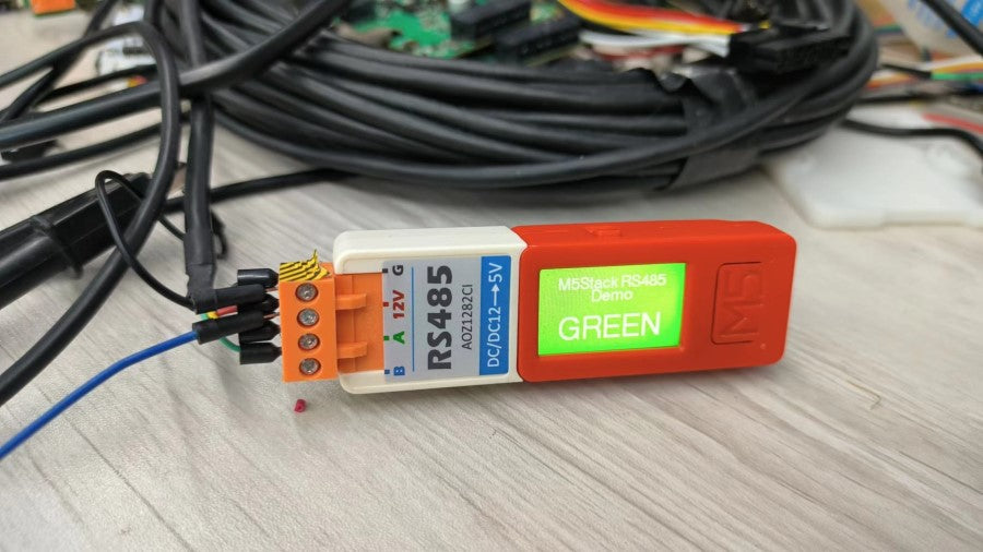
Next, we will use the M5Stack device as an example to demonstrate the application of RS485 communication in IoT. Here we use RS485 HAT, RS485 HAT consists of a 485 automatic transceiver circuit and a DC-DC buck circuit which can drop an input 12V to 5V.

Setting up the Arduino Environment
First, please refer to the Arduino IDE setup tutorial to complete the basic software installation. And then install the `M5Unified and FastLED libraries` in the library manager, or manually clone and install them from the following GitHub links into the C:\Users\PC\Documents\Arduino\libraries directory:
*M5Unified: (https://github.com/m5stack/M5Unified)
*FastLED: (https://github.com/FastLED/FastLED)
Setting up the Hardware Environment
Devices needed:
1. ATOM Matrix x1
2. M5StickC Plus x1
3. RS485 HAT x1
4. Tail485 x1
5.120 Ohm plug-in resistor x1
6. RS485 cable x1
7. 12V power supply x1
Operational steps:
1.Connect the RS485 HAT to the M5stickc Plus.
2. Connect the ATOM Matrix to the Tail485.

3. Connect a 120-ohm matching resistor is needed at the AB end of RS485.

4. Use a 12V power supply.

5. Connect using the RS485 cable.

RS485 Transmitter
Using the following code, we will utilize the M5stickc Plus + RS485 HAT to create an RS485 transmitter. Pressing button A will send control commands via RS485 to control the color of the receiving end's RGB light.
#include "M5Unified.h"
String command[3] = {"RED\n", "GREEN\n", "BLUE\n"};
uint8_t command_index = 0;
void setup() {
M5.begin();
M5.Display.setEpdMode(epd_mode_t::epd_fastest);
M5.Display.setFont(&fonts::Font4);
M5.Display.setTextColor(WHITE);
if (M5.Display.width() < M5.Display.height())
{ /// Landscape mode.
M5.Display.setRotation(M5.Display.getRotation() ^ 1);
}
M5.Display.startWrite();
M5.Display.setTextSize(1);
M5.Display.drawCenterString("M5Stack RS485", M5.Display.width()/2, M5.Display.height()/8);
M5.Display.drawCenterString("Demo", M5.Display.width()/2, M5.Display.height()/8+20);
M5.Display.setTextSize(1);
M5.Display.drawCenterString("btnA send command", M5.Display.width()/2, M5.Display.height()/8+60);
M5.Display.endWrite();
Serial2.begin(115200, SERIAL_8N1, 26, 0);
while (1)
{
M5.update();
M5.Display.startWrite();
if (M5.BtnA.wasClicked()) {
command_index++;
if (command_index > 2)
command_index = 0;
Serial2.printf("%s", command[command_index].c_str());
switch (command_index)
{
case 0:
M5.Display.clear(RED);
break;
case 1:
M5.Display.clear(GREEN);
break;
case 2:
M5.Display.clear(BLUE);
break;
default:
break;
}
M5.Display.setTextSize(1);
M5.Display.drawCenterString("M5Stack RS485", M5.Display.width()/2, M5.Display.height()/8);
M5.Display.drawCenterString("Demo", M5.Display.width()/2, M5.Display.height()/8+20);
M5.Display.setTextSize(2);
M5.Display.drawCenterString(command[command_index], M5.Display.width()/2, M5.Display.height()/8+60);
M5.Display.endWrite();
break;
}
}
}
void loop() {
M5.update();
M5.Display.startWrite();
if (M5.BtnA.wasClicked()) {
command_index++;
if (command_index > 2)
command_index = 0;
Serial2.printf("%s", command[command_index].c_str());
switch (command_index)
{
case 0:
M5.Display.clear(RED);
break;
case 1:
M5.Display.clear(GREEN);
break;
case 2:
M5.Display.clear(BLUE);
break;
default:
break;
}
}
M5.Display.setTextSize(1);
M5.Display.drawCenterString("M5Stack RS485", M5.Display.width()/2, M5.Display.height()/8);
M5.Display.drawCenterString("Demo", M5.Display.width()/2, M5.Display.height()/8+20);
M5.Display.setTextSize(2);
M5.Display.drawCenterString(command[command_index], M5.Display.width()/2, M5.Display.height()/8+60);
M5.Display.endWrite();
}
RS485 Receiver
With the code below, we utilize the ATOM Matrix+Tail485 to create an RS485 receiver. The receiver waits for commands sent by the transmitter and changes the color of the RGB LED.
#include "Arduino.h"
#include <FastLED.h>
#define NUM_LEDS 25
#define DATA_PIN 27
CRGB leds[NUM_LEDS];
char terminateChar = '\n';
const int bufferLength = 100;
char serialBuffer[bufferLength];
String rx_str;
void setup() {
FastLED.addLeds<NEOPIXEL, DATA_PIN>(leds, NUM_LEDS);
Serial2.begin(115200, SERIAL_8N1, 32, 26);
}
void loop() {
if (Serial2.available()) {
Serial2.readBytesUntil(terminateChar, serialBuffer, bufferLength);
rx_str = serialBuffer;
if (rx_str.indexOf("GREEN") != -1) {
for (int i = 0; i < 25; i++)
leds[i] = 0x001000;
FastLED.show();
}
else if (rx_str.indexOf("RED") != -1) {
for (int i = 0; i < 25; i++)
leds[i] = 0x100000;
FastLED.show();
}
else if (rx_str.indexOf("BLUE") != -1) {
for (int i = 0; i < 25; i++)
leds[i] = 0x000010;
FastLED.show();
}
}
}

RS485 Communication in IoT: Bridging the Gap Between Devices
ESP32 CAM is an ESP32 development board with a built-in camera. It is powerful, compact, and suitable for Internet of Things (IoT) projects. It can meet the market's demands for device connectivity, data transmission, and security. The ESP32 CAM offers the following advantages:
Powerful processing capabilities and rich features: ESP32 CAM integrates a high-performance ESP32 chip, providing powerful processing capabilities and various functional modules such as Wi-Fi, Bluetooth, and a camera. This enables easy device connectivity and data processing, meeting the requirements of IoT projects.
Stable wireless connection: ESP32 CAM has a built-in robust Wi-Fi module, offering a stable and reliable wireless connection. This facilitates reliable communication between devices and supports remote monitoring and control functionality.
Flexible device integration: ESP32 CAM has ample GPIO pins and communication interfaces, allowing for flexible integration with other sensors, actuators, and external devices. This simplifies the expansion and customization process of IoT projects.
Security assurance: ESP32 CAM supports secure data transmission and communication protocols such as SSL/TLS. Additionally, being open-source and having an active developer community ensures timely fixes and updates for security vulnerabilities, providing reliable security assurance.
Due to the advantages of the ESP32 CAM, it has a wide range of applications in IoT projects. It can be used in areas such as smart homes, industrial automation, smart agriculture, and smart cities. For example, leveraging the high-performance camera and image processing capabilities of the ESP32 CAM, intelligent video surveillance and facial recognition systems can be implemented.
In the following, we'll use the M5Stack TimerCam as an example and provide a guide to help you set up your own video surveillance project.

We will provide tutorials for four different uses: Web camera, scheduled wake-up capture, push and pull RTSP streaming. However, before getting started, it is necessary to set up the Arduino working environment.
To set up the Arduino environment, we can complete the basic software installation by following the first step in the Arduino IDE environment setup tutorial. And then install the "M5Stack board management" and the "TimerCam-Arduino library" in the Library Manager, or manually clone it from the GitHub link and install it into the "C:\Users\PC\Documents\Arduino\libraries" directory.
1. Set up your webcam
1). Using the code below, we will explain how to initialize the camera, capture a frame of image data, and enable the Webserver Demo for image preview.
// Include the necessary header files
#include "battery.h"
#include "esp_camera.h"
#include <WiFi.h>
#include "soc/soc.h"
#include "soc/rtc_cntl_reg.h"
#include "camera_pins.h"
//Configure the Wi-Fi information for the camera to connect to
const char *ssid = "******";
const char *password = "******";
void startCameraServer( );
void setup( ) {
}
void loop() {
// After startup, you can view the IP address assigned to the camera by serial communication. Here's the code that will continuously print the IP address for easy viewing
Serial.print("Camera Ready! Use 'http://");
Serial.print(WiFi.localIP());
Serial.println("' to connect");
delay(1000);
digitalWrite(2, HIGH);
delay(1000);
digitalWrite(2, LOW);
}
2). Modify the code with the WiFi information section, and compile and burn the program to the device. Then, you can use the serial monitor to view the IP address assigned to the camera.
WiFi connected
Camera Ready! Use 'http://192.168.31.11' to connect
For devices on the same network, you can access 192.168.31.11 through a web browser to access the control page, where can obtain real-time images and adjust image properties.
(Note: You need replace the IP address with the actual IP address printed on the serial monitor).

2. Scheduled wake-up capture
To achieve scheduled wake-up and capture using the RTC (Real-Time Clock) functionality for extended battery life, you can refer the code below. It captures an image during the period between camera startup and entering sleep mode. You can then transmit the image data to another location using a method such as HTTP POST for scheduled capture.
#include "battery.h"
#include "esp_camera.h"
#include <WiFi.h>
#include "soc/soc.h"
#include "soc/rtc_cntl_reg.h"
#include "led.h"
#include "camera_pins.h"
#include "bmm8563.h"
void setup() {
Serial.begin(115200);
WRITE_PERI_REG(RTC_CNTL_BROWN_OUT_REG, 0); // disable detector
bat_init();
led_init(CAMERA_LED_GPIO);
bmm8563_init();
// Configuration of the camera includes settings for pins, image size, and compression format.
// Setting a large image size or high image quality may result in insufficient memory allocation, leading to initialization failure.
camera_config_t config;
config.ledc_channel = LEDC_CHANNEL_0;
config.ledc_timer = LEDC_TIMER_0;
config.pin_d0 = Y2_GPIO_NUM;
config.pin_d1 = Y3_GPIO_NUM;
config.pin_d2 = Y4_GPIO_NUM;
config.pin_d3 = Y5_GPIO_NUM;
config.pin_d4 = Y6_GPIO_NUM;
config.pin_d5 = Y7_GPIO_NUM;
config.pin_d6 = Y8_GPIO_NUM;
config.pin_d7 = Y9_GPIO_NUM;
config.pin_xclk = XCLK_GPIO_NUM;
config.pin_pclk = PCLK_GPIO_NUM;
config.pin_vsync = VSYNC_GPIO_NUM;
config.pin_href = HREF_GPIO_NUM;
config.pin_sscb_sda = SIOD_GPIO_NUM;
config.pin_sscb_scl = SIOC_GPIO_NUM;
config.pin_pwdn = PWDN_GPIO_NUM;
config.pin_reset = RESET_GPIO_NUM;
config.xclk_freq_hz = 20000000;
config.pixel_format = PIXFORMAT_JPEG;
config.frame_size = FRAMESIZE_UXGA;
config.jpeg_quality = 10;
config.fb_count = 2;
// Initialize the camera
esp_err_t err = esp_camera_init(&config);
if (err != ESP_OK) {
Serial.printf("Camera init failed with error 0x%x", err);
return;
}
sensor_t *s = esp_camera_sensor_get();
// Initially flip the sensor vertically and adjust brightness and saturatio
s->set_vflip(s, 1); // flip it back
s->set_brightness(s, 1); // up the blightness just a bit
s->set_saturation(s, -2); // lower the saturation
// Set Frame Size
s->set_framesize(s, FRAMESIZE_QVGA);
camera_fb_t *fb = NULL;
esp_err_t res = ESP_OK;
// Get a frame of image data
fb = esp_camera_fb_get();
if (!fb) {
Serial.println("Camera capture failed");
}
Serial.println("Camera capture OK");
// Acquired image data
uint8_t *data_buffer = fb->buf;
size_t data_len = fb->len;
//...................
// You can perform data processing in this section and send it to the server using the HTTP method.
//...................
// Set a 5-second wake-up interval.
bmm8563_setTimerIRQ(5);
delay(1000);
}
void loop( ) {
// Power off.
// The device enters sleep mode and wakes up after 5 seconds to start executing the program from the beginning. (This only applies when powered by a battery.)
bat_disable_output();
}
3. Push and pull RTSP streaming
RTSP, short for Real-Time Streaming Protocol, is a network transmission protocol used to control the real-time transmission of data in multimedia applications. It is commonly used in conjunction with streaming media servers and clients to achieve real-time streaming and playback of audio and video content. Here is a brief description of the applications of RTSP and the meanings related to push and pull:
RTSP Applications:
Streaming Media Transmission: RTSP is widely used in streaming media applications such as online video streaming, video-on-demand, and video conferencing. It enables clients to work collaboratively with streaming media servers by negotiating session parameters, controlling playback status, and data transmission methods, thus achieving real-time media data transmission and playback.
Surveillance Systems: RTSP is commonly used in surveillance cameras and camera systems, allowing users to remotely monitor video streams over the network. This is particularly useful for home security, enterprise security, and public safety.
Video Conferencing: RTSP is used in video conferencing applications, allowing multiple participants to share audio and video data in real-time, enabling remote collaboration.
Audio Streaming: RTSP not only supports video streaming but also facilitates the transmission of audio streams. This is important for applications such as audio broadcasting and audio conferences.
Push and Pull
Push: Push refers to the process of sending multimedia data (typically audio and video) from a source to the network, allowing other devices or users to access and play it in real-time. Typically, the media source generates data and then pushes it to a streaming media server using a streaming media transfer protocol (such as RTSP, RTMP, HLS, etc.). The process from the source to the server is called "push".
Pull: Pull refers to the process of retrieving multimedia data from a streaming media server and decoding and playing it at the receiving end. Users or client devices request specific media content from the streaming media server using the same streaming media transfer protocol. This process is called "pull".
In summary, RTSP is an essential protocol for real-time streaming transmission widely used in the multimedia domain, enabling users to transmit and play audio and video data in real-time over the internet. Push involves sending media data to the network, while pull involves retrieving and playing media data from the network. Together, they form the core of streaming media services.
Using the Camera as an RTSP Server
By running the examples -> rtsp_stream code, you can configure the device as an RTSP server. Devices on the same network can access the real-time image by using a media player (such as VLC Player) and accessing rtsp://192.168.xxx.xxx:8554/mjpeg/1 (Note: Please replace the IP address with the actual IP address obtained from the serial monitor).
« ..WiFi connected
RTSP URL: rtsp://192.168.2.175:8554/mjpeg/1
LinkedListElement (0x3ffdb9ac)->(0x3ffdb9ac)->(0x3ffdb9ac)
Creating TSP streamer
Created streamer width=640, height=480
Relevant Links
rtsp_stream relies on the Micro-RTSP library, which can be installed by following the dependency prompts when installing the TimerCam-arduino library. Alternatively, you can manually clone and install it using the GitHub link provided. VLC Player is a powerful media player that we will use for pulling/streaming tests in the subsequent testing phase.
- Micro-RTSP
- VLC player
VLC Player Pull Streaming


Configuration of Streaming Relay Server
Distributing HTTP Streaming Sources
In the previous demo, we used the camera as an RTSP server, but there are limitations in terms of performance, especially when multiple clients want to pull the stream, it can be challenging. In some cases, you may want to distribute media resources to external servers or live streaming platforms, or achieve stronger multi-device access capabilities. In the following, we will use an open-source RTSP server project combined with the ffmpeg tool to implement streaming (forwarding TimerCAM data to the server) and pulling (clients pulling video resources from the server).
Here we need to burn the camera with the first web_cam demo program mentioned at the beginning of the article, and we can directly access the image stream through http://IP:81/stream.
Visit EasyDarwin - Github releases, download the release version to your local machine, and extract it. Run it as a service and start the server. (Note: Please use the sudo command to run it, otherwise, you may not have permission to open the port.)
cd EasyDarwin
sudo ./start.sh
#sudo ./stop.sh
Then please use ffmpeg to configure forwarding, and use the IP and port used in the previous demo for TimerCAM's running port and IP. The latter is the IP of the RTSP server (EasyDarwin) (default port 554, followed by a customizable ID number).
Note: Before executing this command, make sure to start the camera and ensure that the image can be previewed correctly on the webpage.
ffmpeg -re -i http://192.168.2.175:81/stream -rtsp_transport tcp -vcodec h264 -f rtsp rtsp://192.168.2.89:554/666
After completing the previous configuration, open a browser and enter http://IP:10008 to access the EasyDarwin control page. The default username and password are admin/admin. (Replace IP with the IP address of the Linux host).

By refreshing the page, we can see a new streaming address added to the control page. We can use general media player software such as VLC to fill in the corresponding streaming address to pull the video and locally cache the recording. Additionally, you can use multiple clients simultaneously for streaming playback.

Distributing Pull Sources
If the camera is being used as an RTSP server, you can also directly configure the pull forwarding in the EasyDarwin backend. For more details, please refer to the EasyDarwin GitHub repository.


What is ESP32 CAM Used For?
The biggest contributor to indoor air pollution is not formaldehyde or PM2.5 but the often-overlooked carbon dioxide. Once carbon dioxide reaches a certain level, it can pose a serious health risk, and no air purifier can effectively filter it. It is crucial to understand the health hazards, normal ranges, and solutions regarding indoor carbon dioxide concentrations.
What are the typical indoor and outdoor carbon dioxide concentrations? Within the normal range, carbon dioxide is harmless to the human body. In the natural environment, the concentration of carbon dioxide is approximately 0.04% (400 PPM), which may reach around 500 PPM in urban areas. In unoccupied indoor environments, the carbon dioxide concentration usually ranges from 500 to 700 PPM.
At what PPM level does carbon dioxide become harmful to health? The human body is highly sensitive to increases in carbon dioxide, with every 0.5% increase noticeably affecting the body. When the concentration reaches 1% (1000 PPM), individuals may experience stuffiness, lack of concentration, and palpitations. At 1500-2000 PPM, symptoms such as breathlessness, headaches, and dizziness may occur. Concentrations exceeding 5000 PPM can lead to cognitive impairment and confusion.
In real-life scenarios, carbon dioxide concentrations often exceed safe levels. For instance, when two individuals sleep overnight in a sealed bedroom, carbon dioxide concentrations can easily reach 2000 PPM. When the carbon dioxide concentration in an office space reaches 2000 PPM, employees may experience fatigue, lack of concentration, and mental exhaustion. Beyond 2000 PPM, individuals may even feel disinclined to continue working, and their cognitive abilities can significantly decline.
Maintaining good ventilation, regularly opening windows for fresh air and using air purifiers are effective methods of reducing indoor carbon dioxide levels. Among these methods, the carbon dioxide sensor is an important tool.
Today, we are introducing two CO2 measuring sensors for detecting carbon dioxide concentrations: CO2L Unit and TVOC/eCO2 Unit.

CO2L Unit is a digital CO2 concentration detection unit with a low-power mode designed for single-shot measurements. It features the Sensirion SCD41 sensor and a voltage regulator circuit, and communicates via I2C. This unit is suitable for measuring environmental conditions, with a typical accuracy of ±(40 ppm + 5% of the reading) for CO2 measurements. The measurement range for CO2 is 400 ppm to 5000 ppm, and it can also measure ambient temperature and humidity simultaneously.
TVOC/eCO2 mini Unit is a digital multi-pixel gas sensor unit that integrates the SGP30 sensor internally. It is primarily designed for measuring the concentrations of various volatile organic compounds (VOCs) and H2 in the air. Through programming, it allows for the measurement of TVOC (Total Volatile Organic Compounds) and eCO2 (Equivalent Carbon Dioxide) concentrations. The typical measurement accuracy within the measurement range is 15%. The SGP30 sensor communicates using the I2C protocol and has an on-chip humidity compensation feature that can be enabled with an external humidity sensor. The SGP30 also has a built-in calibration function, allowing users to calibrate it based on known measurement sources. Once internally calibrated, the SGP30 provides stable long-term output. Additionally, it's important to note that eCO2 is derived from H2 concentration, so the TVOC/eCO2 mini Unit cannot fully replace a CO2 sensor.
CO2 Monitoring Solution:
Here, we will introduce three methods to monitor the CO2 levels in the environment using the CO2L Unit and TVOC/eCO2 Unit and display the data on M5Stack Basic.
Method one: Use EasyLoader to get started.
This is the simplest and fastest way, let’s get it started!
Steps:
1. Open the documentation for the CO2L Unit and TVOC/eCO2 Unit .
2. Download the Easyloader program for each unit, which is a quick verification program.


3. Click to install when the download is complete.

4. Select the port (here we choose COM34, but it's worth noting that different computers may display different COM ports, so please select the appropriate port), then click "burn" to start the program burning process.


It’s downloading and burning now. Once completed, the screen will display "Successfully".

Then, the sensor will begin collecting carbon dioxide data from the air and display it on the Basic. The display effect will be as shown in the following image.


Method two: using source code in Arduino IDE
Next, I’ll lead the way to burn the firmware using the source code. We will use Arduino IDE as the programming environment.
Program CO2L Unit in Arduino IDE
1. The first step is to install the M5Stack development board in the Arduino IDE, which has been covered in our previous article.
2. Open the official documentation for the CO2L Unit , where we provide information about CO2L Unit and its relative code.

3. At the bottom of the documentation page, there are links to download the Arduino sample code. Since we are using the Core series Basic host today, please click on the first link.

4. Open the link and go to the entire project file.

5. Please click on the "Code" here to download the compressed file.

6. Please extract the compressed file into the "libraries" folder within the Arduino installation directory.

7. Open Arduino IDE, and click File>Examples>M5Unit-ENV>Unit_CO2_M5Core

8. Select the board

Select M5Stack-Core-ESP32 and the corresponding port (in this case, it is COM34, but the COM port may differ on different computers). Click OK.

9. Click the right arrow icon to upload the code.


When the upload is complete, we can see that the M5Stack Basic host screen is already displaying the CO2 concentration, as shown in the picture.

ProgramTVOC/eCO2 Unit in Arduino IDE
Next, we will continue to use the TVOC/eCO2 Unit to display the CO2 concentration.
1. Similarly, the first step is to install the M5Stack development board in the Arduino IDE, which has been covered in our previous article .
2. Open the documentation for the TVOC/eCO2 Unit. You can find information about the product and related code.

3. At the bottom of the documentation, there is a link to download the code.

4. Open the link and go to the entire project file.

5. Please click on the "Code" here to download the compressed file.

6. Please extract the downloaded installation package into the "libraries" folder within the Arduino installation directory.

7. Open Arduino IDE, and click File>Examples>M5Stack>Unit>TVOC-SGP30

8. Select the board


Select M5Stack-Core-ESP32 and the corresponding port (in this case, it is COM34, but the COM port may differ on different computers). Click OK.
9. Click the right arrow icon to upload the code.


When the upload is complete, we can see that the M5Stack Basic host screen is already displaying the CO2 concentration, as shown in the picture.

Method three: using EasyLoader to get started
Finally, we introduce M5Stack’s graphical programming software UIFlow. It is convenient for those who are not familiar with coding.
1.To begin with, you need to install the firmware burning tool "Burner".
Note that different operating systems require different versions of Burner to be downloaded.
M5Burner_Windows: https://m5burner.m5stack.com/app/M5Burner-v3-beta-win-x64.zip
M5Burner_MacOS: https://m5burner.m5stack.com/app/M5Burner-v3-beta-mac-x64.zip
M5Burner_Linux: https://m5burner.m5stack.com/app/M5Burner-v3-beta-linux-x64.zip
Note:
For macOS users, after installing Burner, please move the application to the "Applications" folder as shown in the following image.
For Linux users, navigate to the extracted file directory and run "./M5Burner" in the terminal to launch the application.

2. Firmware Burning
Double-click to open the Burner firmware burning tool. In the left-side menu, select the corresponding device category and choose the firmware that matches your device, and click the“Download”button.

Connect the device to your computer using a Type-C data cable. Burner will automatically select the corresponding COM port. You can use the default configuration for the baud rate in M5Burner. Click "Burn" to start the burning process.

During the firmware burning stage, you need to enter the WiFi information in the WiFi configuration box. The WiFi information will be burned and saved to your M5Stack device along with the firmware.
Then, click "Start" to begin the burning process. Note: If a timeout occurs during the burning process, you can try lowering the baud rate to 115200.

When the burning log displays "Burn Successfully," it indicates that the firmware has been successfully burned.

If this is the first time burning or if the firmware program is running abnormally, you can click on "Erase" in the top right corner to erase the flash memory. In subsequent firmware updates, there is no need to erase again. However, please note that erasing the flash memory will delete the saved Wi-Fi information and refresh the API key.
3. Obtaining API Key
Please connect your M5Stack device to the computer using a Type-C data cable and select the corresponding COM port.
1). Click on "Configuration" to view the API Key information, which will appear in the configuration box. (Please copy and save the API Key as it will be used as credentials for UIFlow communication going forward).

2). Set the "Start Mode" to "Internet Mode." After completing this configuration, the device will automatically restart and enter online programming mode.
3). For further explanation of other configuration options in the configuration box, please refer to the configuration instructions below.


4. M5Burner Configuration Instructions
If you need to modify the configuration file, please connect your M5 device to the computer using a Type-C data cable and select the corresponding COM port. Then, you can click on "Configuration" to make the modifications.
APIKEY: The communication credentials for M5Stack device when using UIFlow web programming.
Start Mode: Configurable startup mode after booting.
Quick Start: Option to enable quick start to skip the startup interface.
Server: Selection of the server.
WiFi: Configuration of WiFi SSID and password.
COMX: Option to enable COMX.LTE network (this feature requires stacking the COMX.LTE module, for detailed instructions, please refer to the "Network Over COM.LTE Tutorial").
APN: Configuration of APN access point for COMX.LTE module.
5. After completing the above steps, you can now start using UIFlow for programming.
Enter the UIFlow website URL in your browser: https://flow.m5stack.com/

Here, we will choose UIFlow 1.0 for now, as the list of supported devices for UIFlow 2.0 is still being expanded.
① In Step 3, we have got an API Key, and here we enter it in the bottom-left corner of the screen.

Then the screen will display “Connected”.

② At the "Add Units" section, add the "CO2L Unit" and select "OK."


Click “Load Examples”

④ Click on "Run" or "Download" (running is for testing the code and you can see the results on the host, but the code will not be saved on the device if power is disconnected. Downloading, on the other hand, will save the code on the device, and it will be retained even if power is disconnected. Choose based on your needs. If you choose to modify the code and upload it again, you will need to re-burn the firmware, which is discussed in Step 2).
The device will now start working as shown in the following image.

For the TVOC/eCO2 mini Unit, just follow the same steps as mentioned above, with the difference being the sensor selection during the unit addition. After completing the addition, select the example code, click "Run," and the device will start functioning normally.


Today's tutorial is complete here.
For an introduction to UIFlow statements, you can refer to https://docs.m5stack.com/en/quick_start/m5core/uiflow.
In the future, we will have a dedicated section specifically for explaining UIFlow statements. Stay tuned for that!

What does a CO2 sensor do?
Source: Svet Kompjutera (World of Computers)
Author: Dejan Petrovic
Link: M5Stack Core2 - Slaganje cigala i u mreži - SVET KOMPJUTERA (sk.rs)
Translate: M5Stack
M5Stack is a company engaged in the production of hardware and software in the field of the Internet of Things (IoT). Their most famous product series is the stackable devices, hence the name. These devices can be microcontroller boards, development boards with screens, sensors, and more. There are various solutions available with different sizes, power, and hardware functionalities (Stack, Stick, Atom). The common feature is that they can be stacked together. This allows for ready-made solutions suitable for different needs and projects. We obtained the Core2 from M5Stack, which is a standalone and complete device.

One impressive aspect of Core2 is the availability and completeness of the hardware and software created by M5Stack...
The Core2 is a compact device, measuring approximately 54x54x16 millimeters and enclosed in a white plastic casing. At the heart of the system lies the Espresif ESP32-D0WDQ6-V3 microcontroller. This dual-core 32-bit Xtensa LX6 chip operates at a frequency of 240 megahertz. M5Stack has added additional memory, including 16 megabytes of flash memory and 8 megabytes of PSRAM.
Unlike typical ESP32 modules found in the market (with onboard antennas), the Core2 doesn't follow that form factor. Instead, it provides an interface for an external antenna, allowing the manufacturer to have flexibility in antenna design. In this case, M5Sttack have opted for a 3D antenna, which is clearly a superior solution compared to a printed antenna. The ESP32 itself can connect to Wi-Fi and Bluetooth, although only one radio can be used at a time, with both sharing the same antenna.
Core2 utilizes a USB-C interface for programming and power supply, which uses the CH9102F UART for communication with a computer and is equipped with a circuit for automatically downloading user programs. There is also a JST connector on the board for the same purpose. It is worth noting that M5Stack can be stacked, and the USB interface can be extended using a cable. Core2 can be powered by a battery, and surprisingly, it is equipped with a 390 milliamp-hour lithium-ion battery integrated into the bottom gray casing cover. The AXP192 chip is responsible for battery management, and this programmable circuit is connected to the ESP32 chip via the I2C interface. The chip controls power consumption and notifies the status through the PWR LED. Additionally, it also allows for device shutdown through software. The SY7088 is used as a boost converter. There are two buttons on the casing, 'RST' and 'PWR', with the latter connected to the AXP192. Furthermore, the Core2 casing is secured with internal hex screws and comes with an accompanying wrench with a data cable.

Core2 comes with a rich set of features, and the bottom cover is labeled with tags. Despite being small, each aspect of the device is clearly marked, including pin layouts and other identifiers. If Core2 is used as a clock, it is equipped with the BM8563 real-time clock (RTC) chip, onnected to the ESP32 via the I2C interface. We haven't utilized the RTC functionality yet, but there are corresponding libraries available on the Arduino IDE. Additionally, there is a microSD card slot, a vibration motor, and a speaker. The speaker faces the NS4168 I2S audio driver, providing excellent sound effects. The motor is directly connected to the AXP192. In Core2, the AXP192 plays a more important role, with many EN pins connected to it. This applies to the NS4168, BM8563, and even the LED.

However, the most notable feature is undoubtedly the 2-inch color screen with an integrated capacitive touchscreen (FT6336U). The screen has a resolution of 320x240 pixels and is driven by the ILI9342C driver. We are very pleased with the screen display; although it may not compare to smartphone screens, it is excellent for the purpose of a development board. If you find that the screen calibration and touch sensitivity are not satisfactory, you can download M5TOOL from the official DOCS page to upgrade the firmware. There are three clearly marked touch areas below the screen that can be programmed as needed.
Core2 is equipped with two expansion ports. The smaller four-pin Grove on the side is actually an I2C interface. Grove is a variant of Seeedstudio, similar to QWIIC, STEMMA, easyC, and others. However, unlike other listed variants, M5Stack's Grove has a wider pin spacing and is not compatible with other brands. At the bottom, there is a large 2x15 female header, which is connected to the unused pins of the ESP32. All labels are clearly printed on the bottom, and Core2 can be powered using regulated voltage through the 5V pin. This header can also be used to stack additional modules, and these modules can have any functionality. Core2 comes with a smaller base (M5GOBottom2) that can fit perfectly into the casing and act as a cover for the header. It features the MPU6886 and SPM1423 chips. The former is a motion-tracking sensor that combines a three-axis accelerometer and gyroscope, while the latter is a microphone.
All M5Stack development boards are available in the ESP32 package in the Arduino IDE. For full hardware functionality, M5Stack provides corresponding Arduino libraries. However, M5Stack recommends adding special support through the JSON software package:
https://m5stack.oss-cn-shenzhen.aliyuncs.com/resource/arduino/package_m5stack_index.json,
which helps reduce the hassle when programming and interacting with the internal hardware of Core2. The same approach applies to libraries added for the specific hardware used, such as M5Core2, through "Include Library -> Manage Libraries...". The list of libraries to be installed is quite long. Hardware management is divided into five sections: AXP192, CORE2 LCD, Button, TOUCH, and RTC, each with its own corresponding and well-documented library available. For example, printing "Hello World" typically requires only a few lines of code:
#include <M5Core2.h>
Void setup(){
M5.begin();
M5.Lcd.print("Hello World!");
}
Void loop(){
}

The graphics API does not adhere to the familiar AdafruitGFX, but it has very detailed documentation and allows for creative freedom. It enables drawing various geometric shapes and also supports loading bitmaps from the microSD card. The documentation page (DOCS) is highly detailed, and we really have no complaints in this regard.
Arduino is not the only starting point for learning programming with this device. M5Stack offers UIFlow, MicroPython, and .NET nanoFramework as alternative options. MicroPython does not have a dedicated compiler but can utilize the general compiler of the ESP32. We are not familiar with this approach and have not had any experience with it. However, the most interesting option is undoubtedly UIFlow (www.flow.m5stack.com). This "programming language" is actually a visual "blocks" language. If you recall our discussion about BBC micro:bit and MakeCode, there are many similarities here. It's similar to MIT App Inventor as well. It's a visual block-based approach but based on Python. Above the toolbar, besides the project name, there is a tab to switch between the "block world" and the "Python world" editors. Before any programming, you need to download the M5Burner tool, which is used to load the necessary firmware and the interface for interacting with the "blocks" into the Core2, as well as local network data. We know that these parameters are not cleared when loading user programs. In addition to input parameters, M5Burner also displays the API key, which is important for establishing a connection between UIFlow and Core2.

Let's continue discussing UIFlow. The top toolbar of UIFlow contains various tools and shortcuts. Here, you can open new projects, save existing projects, and more. However, the most important option is "Settings," where you can select the device, port, and enter the API key. After that, you can choose whether to connect Core2 to the computer via a data cable or program it without connecting the data cable. Yes, Core2 supports wireless programming (Over the Air, OTA), similar to MikroElektronika's CodeGrip (although CodeGrip is actually something else). After opening Core2, three options are displayed on the screen: App, UIFlow, and Setup. We are interested in the second option, where we can choose the programming mode, either USB or Wi-Fi. We choose Wi-Fi and disconnect the USB cable from Core2. There is a detailed tutorial on the assembly of "blocks" on the DOCS page, so we won't go into detail here. The UIFlow interface consists of a left section, which can be called a graphical drag-and-drop screen designer, and the middle section is a strip of basic blocks that we can simply drag into the editor on the right. Once the "construction" is complete, the "modules" are loaded onto Core2 almost instantly (in less than a second) by clicking the "Run" button.

We are absolutely thrilled with the availability of M5Stack in terms of hardware and software. The efforts put into it have yielded significant results. It is fascinating, especially with Core2, as it can be used directly as a finished product without any modifications. For instance, it can display data from a server and more, without even requiring a case. It is evident that it can be flexibly stacked according to needs. What's even more interesting is that it can be programmed anywhere as long as it is connected to the internet. We highly recommend it without a doubt.
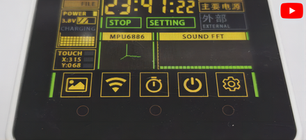
Building with Blocks: Core2 - Unleashing Endless Expansion with ESP32
The ESP32 microcontroller is widely used in IoT projects and offers a flexible and powerful platform for development. Sometimes, people may need to erase the flash memory of their esp32 devices, such as removing existing firmware or preparing the device for new code.
When we are developing our project, we may store some data in the flash, such as when we use the NVS functionality to store information in the flash, but when we need to download new firmware to test this device as a new one, this previous information is not overwritten. So we need to erase the flash completely and then download the new firmware.
In this article, we will lead to erase ESP32 flash memory and provide step-by-step instructions. Here, we introduce a tool called esptool.
To erase the flash memory of an ESP32 device, there are currently three common methods available:
Esptool.py, a command line tool (suitable for MacOS and Linux systems).
Esptool-js, a web-based tool (suitable for MacOS, Linux and Windows systems).
Flash Download Tools, a GUI-based tool based on Esptool (suitable for Windows system).
Next, we will provide detailed instructions for these three tools. In this article, we will use the M5Stack Core2 as an example. The M5Stack Core2 is a popular ESP32-based controller that features a 2.0-inch integrated capacitive touch screen and a wide range of built-in functions.
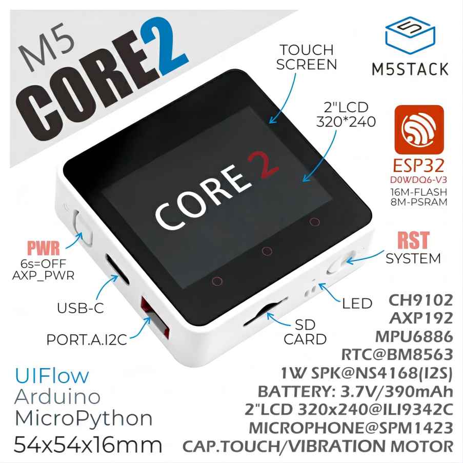
Esptool.py
Introduction:
Esptool.py is a Python-based, open-source, platform-independent utility for communicating with the ROM boot loader in Espressif SoCs.
It can do a number of things, for example:
- Read, write, erase, and verify binary data stored in flash.
- Read chip features and other related data such as MAC address or flash chip ID.
- Read and write the one-time-programmable efuses.
- Prepare binary executable images ready for flashing.
- Analyze, assemble, and merge binary images.
How to use Esptool.py to erase the Flash chip in M5Core2
1). Install esptool.
Open the Terminal application and type the following installation command at the command line.
pip install esptool
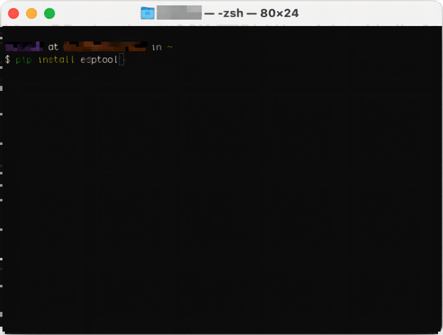 After the installation, we can test it with the following command. If it returns the correct version, it indicates a successful installation.
esptool version
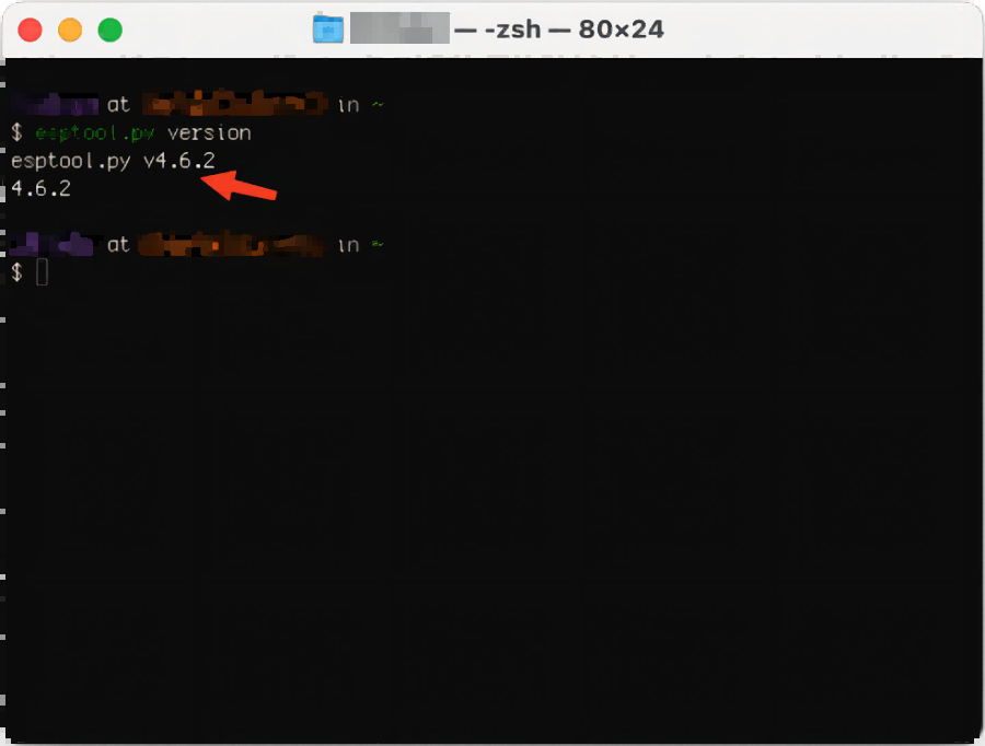
2). Get the PORT number of M5Core2.
Use the following command to find out the USB serial port number of the M5Core2. In this step, please ensure that M5Core2 is the only device connected to your computer.
ls /dev/cu.usb*
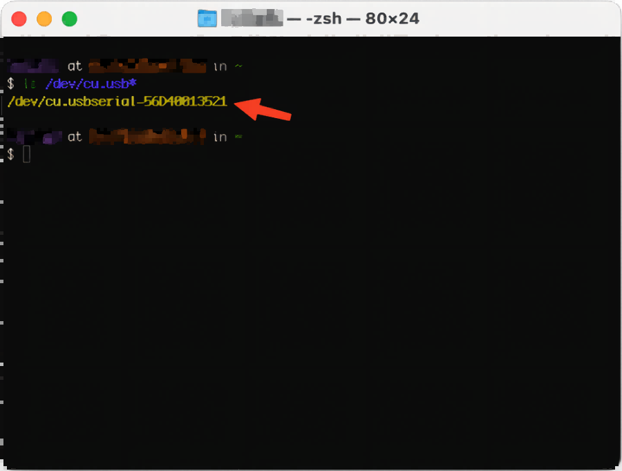
*The serial port number in the image above is for the MacOS system. If your computer is running a different operating system, you will need to replace the serial port number with the appropriate one.
3). Execute the erase command to erase the Flash chip in M5Core2.
esptool.py --chip auto -p /dev/cu.usbserial-56D40013521 erase_flash

The Chip Auto automatically detects the chip type, making it easy to use. When you see the message "Chip erase completed successfully" in the terminal, it indicates a successful erase. The time required for erasing may vary depending on the actual capacity of the flash chip, so please be patient and wait a while. And now we have successfully erased the flash chip in M5Core2.
Esptool-js
Introduction:
Esptool-js is a Javascript implementation of esptool, a serial flasher utility for Espressif chips. esptool-js is based on Web Serial API and works in Google Chrome and Microsoft Edge version 89 or later browsers.
Unlike the Python-based esptool, esptool-js doesn't implement generation of binary images out of ELF files.
In the following steps, we'll erase the ESP32 flash chip using a web-based demo provided by Espressif Systems..
How to use Esptool-js to erase the Flash chip of M5Core2
1). Open the following web link:
ESP Tool (espressif.github.io)

2). Connect M5Core2 with USB cable

Select a lower baud rate and then click the Connect button.

Select the serial port number of M5Core2 in the pop-up window.
3). Erase
Once connected, the next page will show the correct model and version of the M5Core2's ESP32 chip.

Click the Erase Flash button to start erasing the Flash chip!
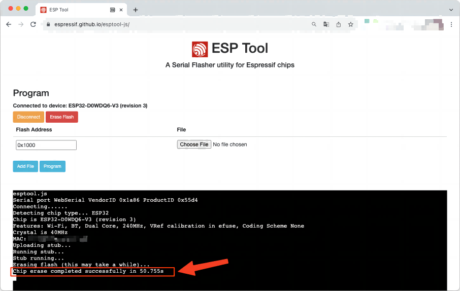
When "Chip erase completed successfully ..." is displayed, it means that the M5Core2 flash chip has been successfully erased. As mentioned earlier, the erasing process may take some time due to the different actual capacities of the flash chip. Please be patient and wait a while. In addition, this website is not limited to the erase function, but also allows you to burn firmware. You can explore this functionality separately, as it is beyond the scope of this discussion.
Now, we have successfully used Esptool-js to erase the Flash chip of M5Core2.
Next, we will present the final method.
Flash Download Tools
Introduction:
Flash Download Tools is a GUI tool designed for the Windows platform. This tool can be used to program not only ESP32 series chips but also chips such as ESP8266 and ESP8285. It also provides batch programming for mass production. In this article, we will only discuss how to erase the flash chip.
To get started, you will need to download the tool from the following link:Tools | Espressif Systems
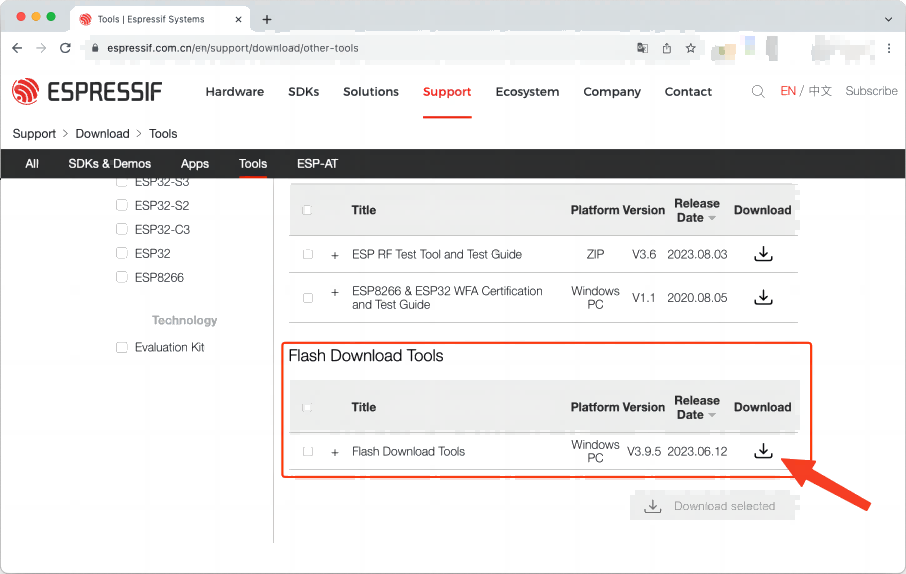
How to use Flash Download Tools to erase the Flash chip of M5Core2
1). We need to extract the downloaded files.
Once the extraction is complete, we will see the list of files shown in the image below.
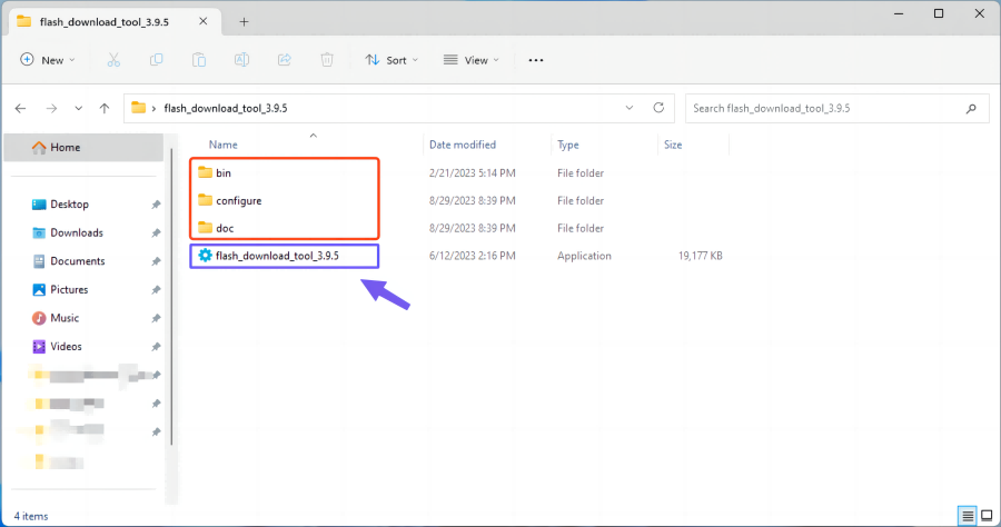
This tool does not need to be installed. You can simply double-click it to run it. The documentation can be found in the red box.
2). View the serial port number in Device Manager
Connect M5Core2 to your computer using a USB cable, and then open Device Manager.
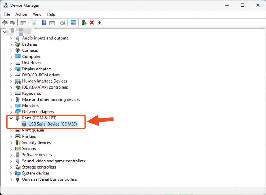
The serial port number here is COM28, the numbers may vary for different devices. Please check the actual serial port number on your computer. If you have multiple devices connected, please disconnect the others and ensure that only one M5Core2 device is connected to the computer.
3). Open the tool and begin to erase!
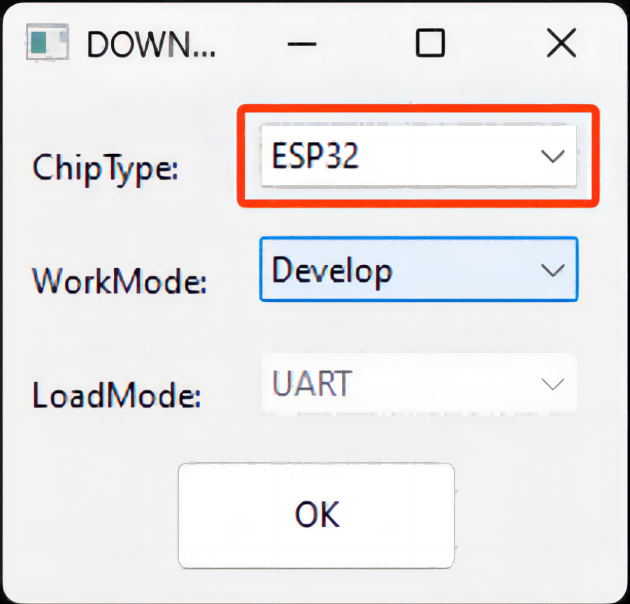
Here we select "ESP32" for ChipType. If you are using a device with a different chip model, select the specific chip model accordingly. For WorkMode and LoadMode you can leave the default options. The tool interface will look like the image below.
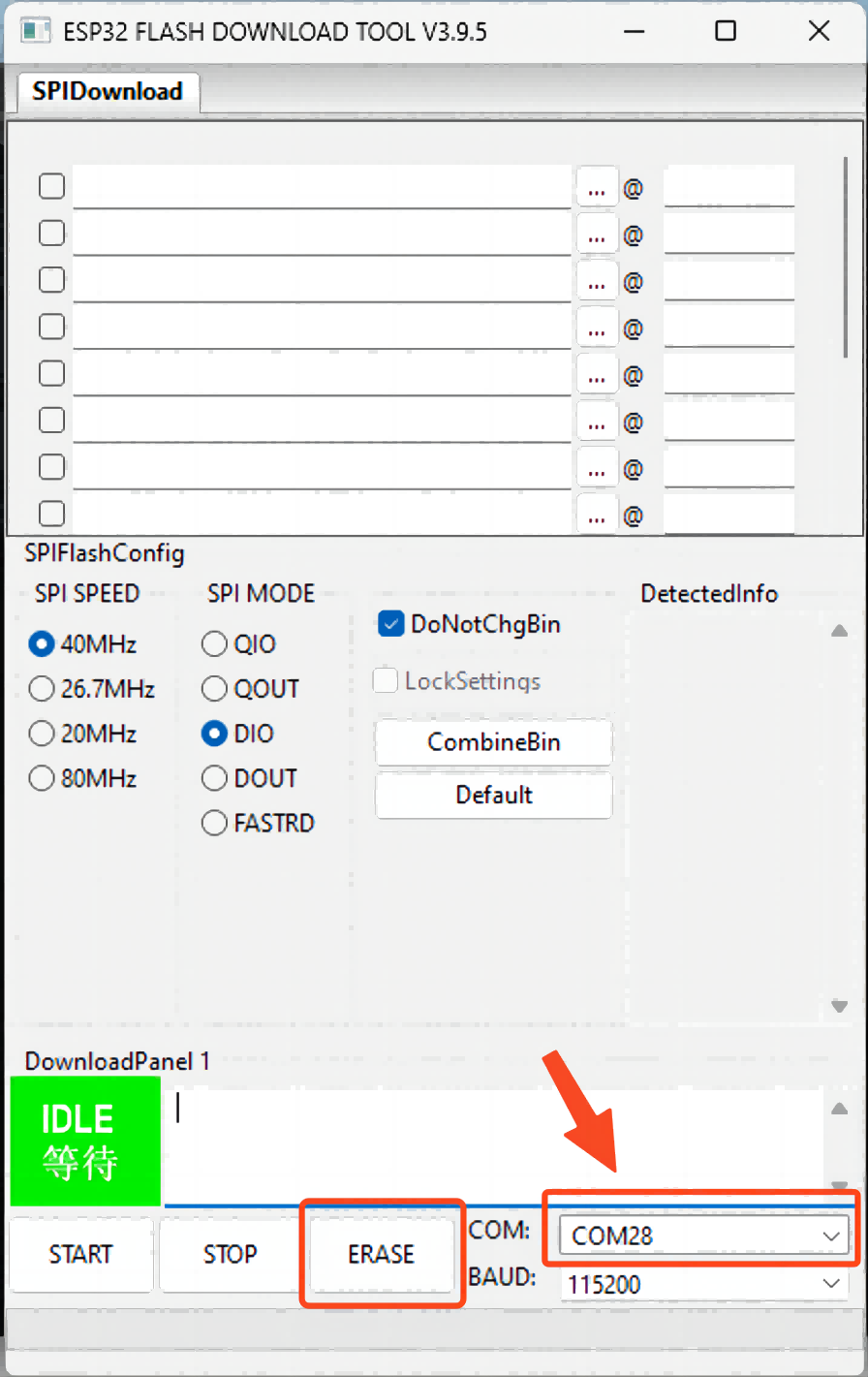
At the bottom right, select the serial port number we checked in step two from the COM drop-down menu. If you have more than one device connected, make sure you do not select the wrong one to avoid accidentally erasing another device's flash or causing an error. Once you have made your selection, click the ERASE button to start the erasing process. Wait a while and when you see "FINISH" it means that the flash chip has been successfully erased.
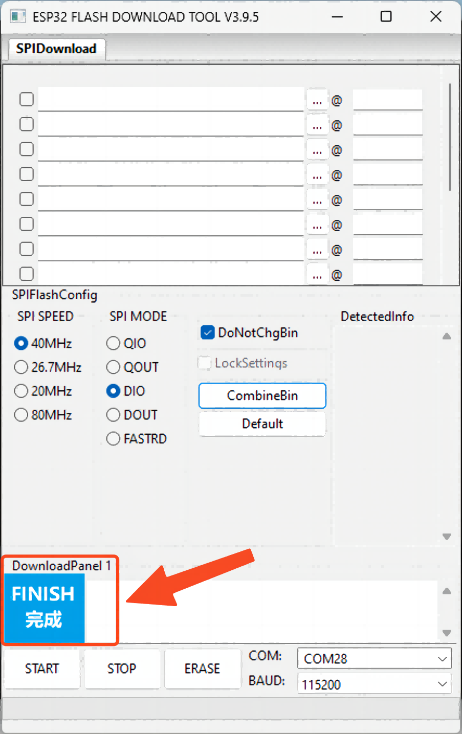
Congratulations! You have successfully used Flash Download Tools to erase the Flash chip in M5Core2.
Summary:
In this tutorial, using M5Core2 as an example, we have presented three methods for erasing the ESP32 flash chip. Each method can be used and you can choose the one that suits you best.

How to Erase ESP32 Flash Memory
We often come across many excellent IoT projects that utilize ESP32 and Arduino. These two platforms clearly hold significant importance. So, what are they, and how can we utilize them together?
Introducing ESP32
ESP32 is a powerful microcontroller module developed by Espressif Systems, which comes with integrated Wi-Fi and Bluetooth connectivity for a wide range of applications, and highly integrating with in-built antenna switches, RF balun, power amplifier, low-noise receive amplifier, filters, and power management modules. It can interface with other systems to provide Wi-Fi and Bluetooth functionality through its SPI / SDIO or I2C / UART interfaces. ESP32 is widely used in mobile devices, wearable electronics and IoT applications.
M5Stack is a renowned company that specializes in providing hardware and software for rapid prototyping and IoT applications. M5Stack products are widely recognized for their integration, simplicity, and versatility, allowing users to stack or connect different modules/units together to build customized and scalable solutions. These modules cover a wide range of functionalities, including displays, sensors, communication interfaces, input devices, and more. By combining these modules, users can quickly create prototypes or even deploy complete IoT systems with minimal effort.
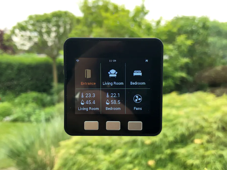
One of the standout features is many M5Stack controllers built around the ESP32, leveraging its powerful processing capabilities, wireless connectivity, and extensive ecosystem. This compatibility grants users access to a vast library of code, examples, and community support, making development with M5Stack devices efficient and user-friendly.
Introducing Arduino
Arduino is an open-source electronics platform based on easy-to-use hardware and software. In the past years, countless of projects, ranging from simple household items to intricate scientific instruments, have used Arduino as their brain. Over time, Arduino has accumulated a vast user base worldwide including students, hobbyists, artists, programmers, and professionals, who have gathered around this open-source platform to contribute an incredible amount of accessible knowledge that can be of great help to novices and experts alike.
How to start
By leveraging the capabilities of both platforms, developers can create innovative IoT projects that benefit from the wireless connectivity of the ESP32 and the ease of development offered by Arduino. This combination opens up possibilities for remote monitoring, home automation systems, sensor networks, and much more.
In this tutorial, we will provide detailed steps and practical tips to help you correctly program ESP32 (take M5Stack Basic for example) with Arduino IDE. Let's start!
1. Download the Arduino IDE
First, go to the Arduino website (https://www.arduino.cc/en/Main/Software) to download Arduino IDE that corresponds to your operating system.
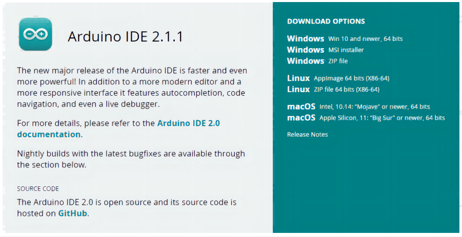
2. Preparing Arduino IDE
① Open the Arduino IDE and go to File -> Preferences -> Settings.
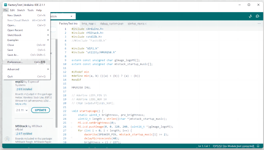
② Copy the following board manager URL and paste it into the Additional Board Manager URLs:
https://raw.githubusercontent.com/espressif/arduino-esp32/gh-pages/package_esp32_dev_index.json
In this turial, we use M5Stack’s development boards,so in this step, just copy the following M5Stack board manager URL and paste it into the Additional Board Manager URLs:https://m5stack.oss-cn-shenzhen.aliyuncs.com/resource/arduino/package_m5stack_index.json
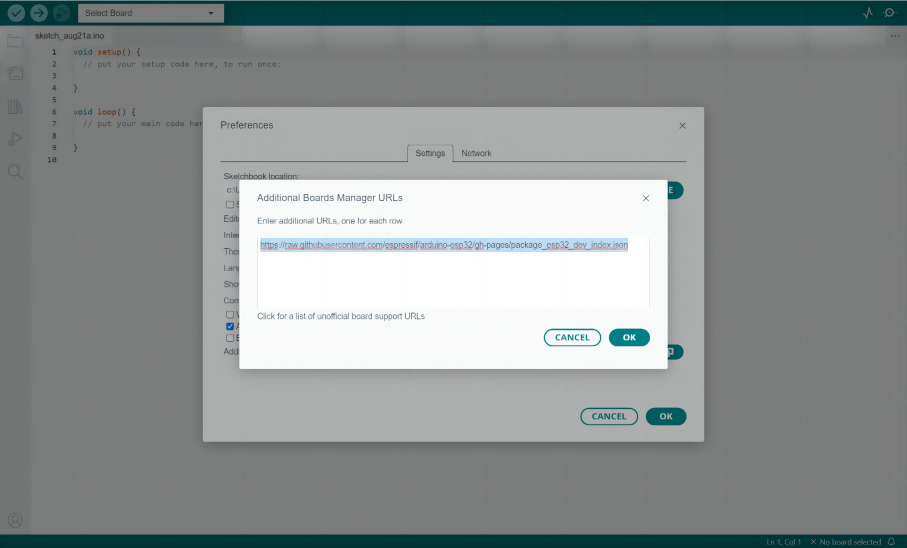
3.Select Tools -> Board -> Board Manager

4. Installing ESP32 Board in Arduino IDE
In this tutorial, M5Stack's Basic Core is an example for leading. Thus, in this step, please enter "M5Stack" in the search field and click Install.
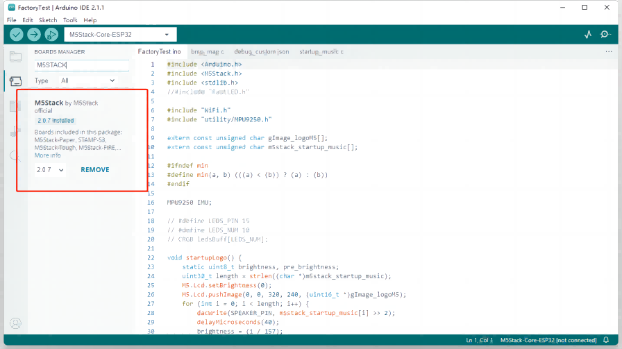
And if you use other ESP32 controllers, please enter "ESP32" in the search field and click Install.
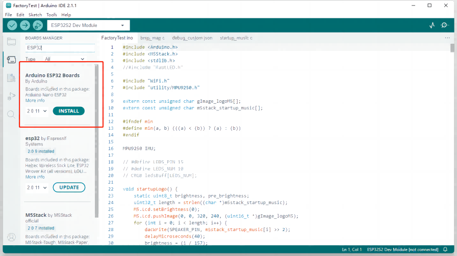
5. Selecting the Board
In this step, please select Tools -> Board -> M5Stack Arduino -> M5Stack-Core-ESP32. And currently, various M5Stack controller options are available for selection.
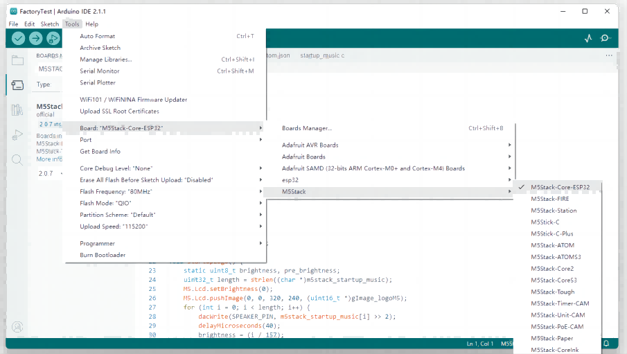
6. Programming ESP32 with Arduino IDE
Now, you can program the device using Arduino IDE and conveniently use it alongside hardware like Arduino Uno to unlock additional functionalities. In this step, an example demo of Basic Core is uploaded, and you can see, the code is synchronized with the device. Now, you can start your own programming projects.
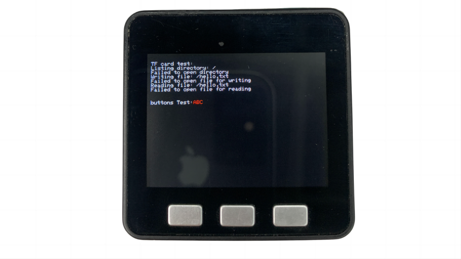

Step-by-Step Guide: How to Program ESP32 with Arduino IDE?
Born on July 2, 2021, the adorable Stack-chan has just celebrated its second birthday!

What is Stack-chan?
The name Stack-chan (スタックチャン) may sound strange, and what is its relationship with M5Stack?
Actually, Stack-chan is an open-source robot project created by a user of M5Stack named Shinya Ishikawa. The name "Stack-chan" comes from the fact that it is built using M5Stack hardware, which is a modular system that allows users to stack different modules together to create custom electronic devices.
"Chan" is the Romanized pronunciation of the Japanese honorific suffix "ちゃん", which is a suffix in Japanese that is often used as a term of endearment or to show familiarity, similar to "dear" or "sweetie" in English.
So, "Stack-chan" is a cute and friendly name that reflects the robot's playful and approachable nature. Due to its cute and interesting appearance, it has gained a lot of popularity among users and even formed a unique subculture.
 The exclusive Twitter account for Stack-chan: https://twitter.com/stack_chan
"It's just so cute, you can't stop loving it."

At first, Shinya Ishikawa simply wanted to create a 100% open-source robot, but he never expected that this little robot would be loved by so many people, and even have the potential for mass production in the future.

Shinya noticed that most of the communication robots on the market are "closed", dependent on specific proprietary services, or their specifications are not disclosed to the public, and reaching the end of life as their backend services go by.

"Why don't they make communication robots more open and hackable?" It is the problem and why Stackchan was born. As a solution, He decided to create an open-source robot that anyone could build from scratch. This means that open community, rather than a closed, specific company or individual, will collaborate to grow the robot.

Based on this idea, in 2021, the prototype of Stack-chan was created. The robot consists of a case, an M5Stack’s controller Basic, which is a modular, stackable, and portable device with an ESP32-based microcontroller, a dedicated expansion board, and firmware. Each component is fully customizable. The functionality as a communication robot is provided in the form of a framework, which users can easily access through applications (mods). M5Basic is equipped with wireless communication functions such as Wi-Fi and BLE, so it can be used with external services, smartphones, and other robots.

The most important feature of Stack-chan is that everything is open.
Stack-chan is open in two aspects.
First, All the resources of Stack-chan are distributed under Apache-2.0 license, including the schematics, the 3D model of the case and the firmware.

Second, Shinya opened up not only the source code and model data for Stack-chan but also the entire process of creating it. In other words, he shared widely the background issues, the decisions I made, the troubles he had, and the mistakes he made so that users can learn how to make and customize Stack-chan. People can follow the process by searching its official Twitter hashtags #stackchan, #スタックチャン on Twitter.
As a result, more than 30 enthusiasts soon began making Stack-chan, with applications ranging from voice assistants to quadruped robots, making Stack-chan's applications diverse and interesting. To date, over 500 users have joined Stack-chan's Discord group.

AI Stack-chan
 https://twitter.com/robo8080/status/1631224076005179393
As more and more users joined, Stack-chan's form and use became more diverse. Earlier this year, Chat-GPT became popular, and many users started trying to connect M5Stack devices to OpenAI's API. User @robo8080 combined Stack-chan and Chat-GPT to create an AI version of Stack-chan. The intelligence level of the AI version of Stack-chan was significantly improved, and it quickly gained a lot of attention and popularity.
 https://twitter.com/lewangdev/status/1675709684664369153
Stack-chan themselves has no special mission to solve. They just live. They have multiple communication modalities such as speech and gaze. In despite of its small size, Stack-chan has a very lifelike appearance with its eyes and breathing.

This behavior is achieved by simulating neurophysiological phenomena such as saccadic eye movements.
But who cares about the detail? However, what truly matters is that everyone treats Stack-chan as a real child and loves it dearly. In fact, some users have even started discussing what style of commemorative shirts to create for Stack-chan.


Stack-chan's Journey: How It Became a Beloved Robot and Created a Subculture