


Product Status Notice This product is EOL (End of Life). Please order the M5StickC Plus and Stick Watch Accessory Kit
Description
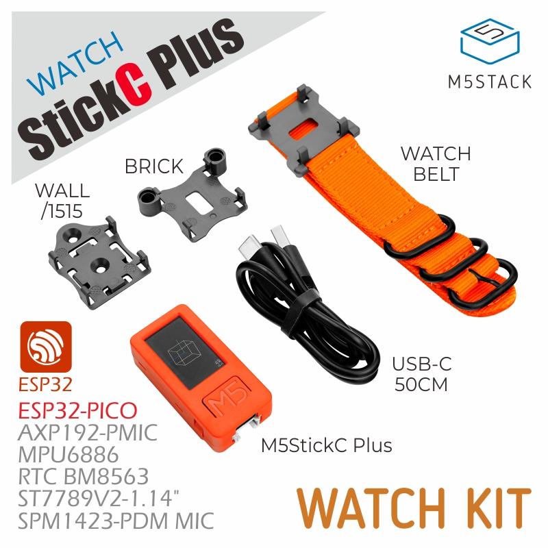
The StickC-Plus Watch Kit is a M5StickC Plus watch set, including the M5StickC Plus IoT development board and a series of watch strap accessories. Based on the powerful hardware resources and expandability of the M5StickC Plus, it can be used not only for time display but also for applications such as motion state monitoring and smart home control. Combined with the M5Stack HAT hardware peripheral system for secondary development, it can further expand the possibilities of smart wearable applications.
Features
- Personalized support for custom display
- 200mAh battery
- Lightweight and portable
Includes
- 1 x StickC-Plus
- 1 x LEGO adapter
- 1 x Wall/1515
- 1 x Watch strap
- 1 x Type-C USB (50cm)

Applications
- Smartwatch

Specifications
| Main Control Resources | Parameters |
|---|---|
| ESP32 | 240MHz dual core, 600 DMIPS, 520KB SRAM, Wi-Fi |
| Flash Memory | 4MB Flash |
| Input Voltage | 5V @ 500mA |
| Interfaces | Type-C x 1, GROVE(I2C+I/O+UART) x 1 |
| LCD Screen | 1.14 inch, 135 x 240 Colorful TFT LCD, ST7789v2 |
| Microphone | SPM1423 |
| Buttons | Custom buttons x 2 |
| LED | Red LED x 1 |
| RTC | BM8563 |
| PMU | AXP192 |
| Buzzer | Onboard buzzer |
| IR | Infrared transmission |
| MEMS | MPU6886 |
| Antenna | 2.4G 3D antenna |
| External Pins | G0, G25/G26, G36, G32, G33 |
| Battery | 120 mAh @ 3.7V, inside vb |
| Strap Size & Weight | 230 x 22 x 6mm / 12.3g |
| Product Size | StickC-Plus: 48.0 x 24.0 x 13.5mm |
| Product Weight | 29.2g |
| Package Size | 126.0 x 67.0 x 22.0mm |
| Gross Weight | 72.5g |
